ABB manipulators
ABB offers a wide range of industrial articulated manipulators, from compact 6-axis robots for small-part handling and payloads of a few kilograms to heavy-duty models capable of lifting up to 800 kg. This guide provides instructions for using ABB robots within the AICA System, focusing on connecting and configuring both simulated environments using RobotStudio and real hardware setups.
To use the ABB collection, add collections/abb v1.0.0 or higher to your configuration in AICA Launcher, currently
supporting the following robot models out of the box:
- IRB 1010
- IRB 6730-210/3.1
- GoFa CRB 15000-12/1.27
Other robot models can be added on request. Reach out to the AICA support team for further information.
General
This guide and the provided drivers are designed for ABB robots connected to OmniCore controllers, whether in simulation or with real hardware. Ensure your setup uses RobotWare for OmniCore for full compatibility with the instructions and features described below.
This collection supports RobotWare versions 7.X and above. For older versions, contact the AICA support team.
Externally Guided Motion
ABB permits remote control of its manipulator range using the Externally Guided Motion (EGM) feature. EGM provides external devices with the ability to send commands and control ABB robotic arms, using Google's Protocol Buffers (Protobuf) serialization library to transport information through UDP sockets. For more information, check out the official product documentation.
EGM is an optional add-in and has to be purchased separately.
Robot Web Services
The second ABB feature that AICA System utilizes to connect to the robot is Robot Web Services (RWS). RWS is a platform that enables developers to create applications that interact with the robot controller, using RESTful APIs that leverage the HTTPS protocol. The hardware interface uses RWS for auxiliary functionality, such as starting/stopping the program and the motors, and setting IOs. Setting up RWS on the simulator and on the actual robot requires slightly different steps, which will be explained in the following sections. More information can be found on the product reference page.
RAPID
RAPID is the programming language of ABB robots. Users can utilize RAPID to set up and execute their workflows and processes. This is enabled by user-defined libraries called Modules, that contain variables and functions or processes (PROCs). Modules can then be loaded in controller Tasks, and called as required.
Connecting to a robot
The hardware interface provided by the ABB collection can be used to control either a simulated or a real robot. The following sections provide the necessary steps to do both.
RobotStudio simulation
RobotStudio is the official ABB offline programming and simulation tool for robotics applications. It allows to run virtual controllers that mimic the behavior of the real robot, ensuring seamless transition between simulation and hardware. It can also be used to configure several aspects of the real controller.
The RobotStudio software suite is available only for Windows, so you may need to set it up on a secondary device or a virtual machine.
Setting up a virtual workstation and controller can be achieved by following the next steps:
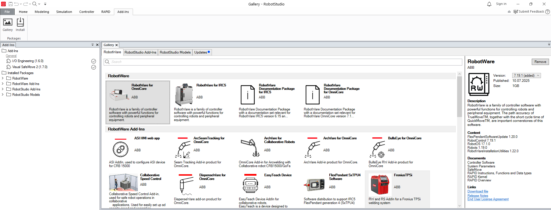
- In RobotStudio, navigate to the Add-Ins tab and go to Gallery. There is a list of all available robot models
and RobotWare versions, the internal controller software. To ensure consistency between simulation and reality, make
sure to install the versions matching the real robot controller, if one is available.
- Go back to to File > New > Project.
- Select to create a new controller and define the robot model and variant, as well as the RobotWare version.
- Make sure to activate the Customize Options button. This is required to add EGM in a next step.
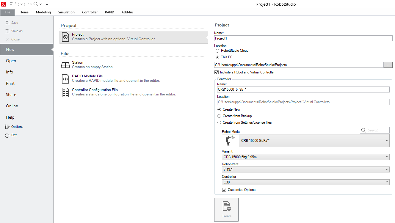
- Select Create to create the new project.
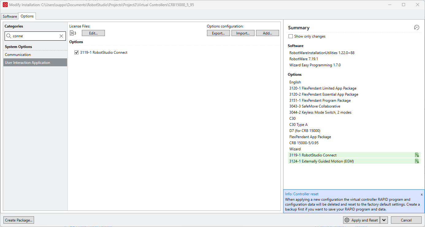
- In the window that pops up, in the Options tab, look for EGM and RobotStudio Connect and add them in the
controller. Then select Apply and Reset to finalize.
note
The 3119-1 RobotStudio Connect add-in is required to connect a controller to RobotStudio over a public network. For more information, see the RobotStudio instruction manual.
- Disable the Windows firewall on the network where the PC running AICA Core is connected to.
- Finally, the PC running AICA Core has to be whitelisted to communicate with RobotStudio. As explained
here,
create a file called
vcconf.xmlunderC:/Users/<user>/AppData/Roaming/ABB Industrial IT/Robotics IT/RobVCwith the content below. Replace<user>in the path above with your Windows user and the IP address in the snippet below with the IP of the PC running AICA Core (in this example 192.168.137.100).vcconf.xml<?xml version="1.0" encoding="UTF-8"?>
<VCConfiguration><RemoteVCConfiguration PublicationEnabled="true"/><hosts><host ip="192.168.137.100"/></hosts></VCConfiguration>
Real robot controller
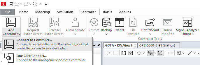
RobotStudio can be used to configure the address of the external control device. Navigate to the Controller tab and select Add Controller > Connect to Controller. This will allow to detect and connect to the running controller in OmniCore, provided of course that the devices are on the same network.
Network and device configuration
Modifications in the real robot controller require write access. To get it, click on Request Write Access and confirm on the pendant's screen. To save these modifications, the controller has to be restarted. While this takes seconds in simulation, the restart procedure in the real robot might take a few minutes, so make all necessary changes, and then restart.
After connecting to the robot, the controller should be configured to accept commands from an external device.
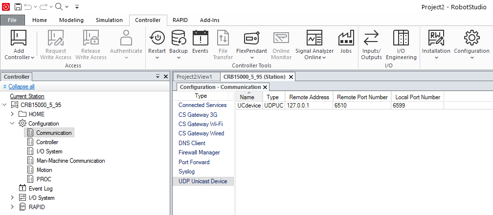
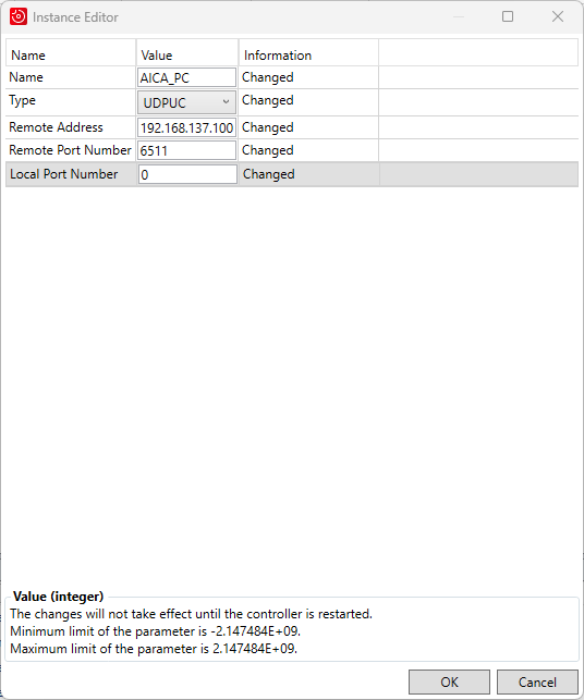
- Navigate to the Controller tab > Configuration > Communication > UDP Unicast Device, and add a new UDPUC device (or
modify the existing one), configured as shown below. This is the PC running AICA Core, the external control device,
so the address should be set accordingly.
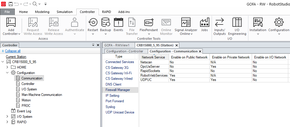
- Navigate to the Controller tab > Configuration > Communication > Firewall Manager, and make sure that UDPUC and
RobotWebServices are enabled in the network that is being used.
- Navigate to the Controller tab > Configuration > I/O System > Signal, and add a new signal as shown below.
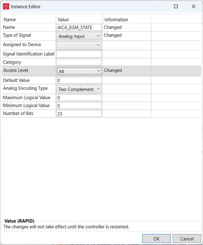
- Finally, for the changes to take effect, restart the controller.
RAPID module
The ABB hardware interface provided by AICA needs a matching RAPID module running on the robot to allow external control through EGM. Place the module below in the controller's home directory and upload it to the current task.
The setup steps above are required for the module to run properly, follow them closely.
AICA_EGM.modx
MODULE AICA_EGM
    LOCAL RECORD EGMSettings
        ! UdpUc device name
        string uc_device;
        ! Time-out for communication with the external UdpUC device in seconds
        num comm_timeout;
        ! The convergence criteria datais used to decide if the robot has reached the ordered joint positions
        num cond_min_max;
        ! Maximum admitted joint speed change in degrees/second
        num max_speed_deviation;
        ! The time in seconds that the convergence criteria defined in EGMActJoint has to
        !   be fulfilled before the target point is considered to be reached
        num cond_time;
        ! Defines in seconds how fast the movement is started
        num ramp_in_time;
        ! Position correction gain. A value between 0 and 1
        num pos_corr_gain;
    ENDRECORD
    LOCAL CONST string CONTEXT_MAIN:="[Main]: ";
    LOCAL CONST string CONTEXT_EGM:="[EGM]: ";
    LOCAL CONST num STATE_IDLE:=0;
    LOCAL CONST num STATE_INITIALIZE:=1;
    LOCAL CONST num STATE_RUN_EGM:=2;
    LOCAL VAR num current_state;
    LOCAL VAR errnum CHANGE_STATE:=-1;
    LOCAL VAR num idle_counter:=0;
    LOCAL VAR intnum intnum_start_egm;
    LOCAL VAR intnum intnum_stop_egm;
    LOCAL VAR intnum intnum_restart_egm;
    ! EGM settings
    LOCAL CONST string DEFAULT_UC_DEVICE:="UC_DEVICE";
    LOCAL VAR egmident egm_id;
    LOCAL VAR EGMSettings settings;
    LOCAL VAR egm_minmax minmax_condition;
    LOCAL VAR bool egm_setup;
    LOCAL VAR jointtarget current_j;
    PROC main()
        TPErase;
        initialize;
        printInfoMessage 0, CONTEXT_MAIN, "Starting StateMachine loop";
        WHILE TRUE DO
            TEST current_state
                CASE STATE_RUN_EGM:
                    runEGM;
                DEFAULT:
                    runIdle;
            ENDTEST
            WaitTime 0.01;
        ENDWHILE
    ERROR(CHANGE_STATE)
        idle_counter:=0;
        TRYNEXT;
    ENDPROC
    LOCAL PROC initialize()
        IDisable;
        BookErrNo CHANGE_STATE;
        IDelete intnum_stop_egm;
        CONNECT intnum_stop_egm WITH handleStopEGM;
        ISignalAI AICA_EGM_STATE, AIO_BELOW_LOW, 1.5, 0.5, 0, intnum_stop_egm;
        IDelete intnum_start_egm;
        CONNECT intnum_start_egm WITH handleStartEGM;
        ISignalAI AICA_EGM_STATE, AIO_BETWEEN, 1.5, 0.5, 0, intnum_start_egm;
        IDelete intnum_restart_egm;
        CONNECT intnum_restart_egm WITH handleRestartEGM;
        ISignalAI AICA_EGM_STATE, AIO_BETWEEN, 2.5, 1.5, 0, intnum_restart_egm;
        current_state:=STATE_IDLE;
        EGMReset egm_id;
        EGMGetId egm_id;
        egm_setup:=FALSE;
        settings.uc_device:=DEFAULT_UC_DEVICE;
        settings.comm_timeout:=1;
        settings.cond_min_max:=0.1;
        settings.max_speed_deviation:=120; ! lowest axis speed on GoFa 12kg
        settings.cond_time:=5;
        settings.ramp_in_time:=1;
        settings.pos_corr_gain:=1;
        IEnable;
    ENDPROC
    LOCAL PROC runEGM()
        IF NOT egm_setup THEN
            printInfoMessage 2, CONTEXT_EGM, "Wait until zero speed";
            WaitRob\ZeroSpeed;
            minmax_condition.min:=-Abs(settings.cond_min_max);
            minmax_condition.max:=Abs(settings.cond_min_max);
            EGMSetupUC ROB_ID, egm_id, "default", settings.uc_device \Joint \CommTimeout:=settings.comm_timeout;
            EGMActJoint egm_id
                        \J1:=minmax_condition
                        \J2:=minmax_condition
                        \J3:=minmax_condition
                        \J4:=minmax_condition
                        \J5:=minmax_condition
                        \J6:=minmax_condition
                        \MaxSpeedDeviation:=settings.max_speed_deviation;
            printInfoMessage 2, CONTEXT_EGM, "EGM set up";
            egm_setup:=TRUE;
        ENDIF
        IF egm_setup AND EGMGetState(egm_id)=EGM_STATE_CONNECTED THEN
            printInfoMessage 2, CONTEXT_EGM, "Starting EGM";
            saturateValue settings.pos_corr_gain, 0, 1;
            EGMRunJoint egm_id,
                        EGM_STOP_HOLD
                        \J1\J2\J3\J4\J5\J6
                        \CondTime:=settings.cond_time
                        \RampInTime:=settings.ramp_in_time
                        \PosCorrGain:=settings.pos_corr_gain;
            printInfoMessage 2, CONTEXT_EGM, "EGMRunJoint terminated";
        ENDIF
    ERROR
        IF ERRNO=ERR_UDPUC_COMM THEN
            printInfoMessage 2, CONTEXT_EGM, "Communication timeout";
            egm_setup:=FALSE;
            TRYNEXT;
        ENDIF
    ENDPROC
    LOCAL PROC runIdle()
        IF idle_counter MOD 1000 = 0 THEN
            printInfoMessage 0, CONTEXT_MAIN, "Idling...";
            idle_counter:=0;
        ENDIF
        Incr idle_counter;
    ERROR
        RAISE;
    ENDPROC
    LOCAL TRAP handleStopEGM
        printInfoMessage 0, CONTEXT_MAIN, "Handling EGM stop";
        IF current_state=STATE_RUN_EGM AND EGMGetState(egm_id)=EGM_STATE_RUNNING THEN
            EGMStop egm_id,EGM_STOP_HOLD;
            current_state:=STATE_IDLE;
            RAISE CHANGE_STATE;
        ENDIF
        printInfoMessage 0, CONTEXT_MAIN, "EGM stop is not possible";
    ERROR (CHANGE_STATE)
        RAISE CHANGE_STATE;
    ENDTRAP
    LOCAL TRAP handleStartEGM
        printInfoMessage 0, CONTEXT_MAIN, "Handling EGM start";
        IF current_state=STATE_IDLE THEN
            current_state:=STATE_RUN_EGM;
            RAISE CHANGE_STATE;
        ENDIF
        printInfoMessage 0, CONTEXT_MAIN, "EGM start is not possible";
    ERROR (CHANGE_STATE)
        RAISE CHANGE_STATE;
    ENDTRAP
    LOCAL TRAP handleRestartEGM
        printInfoMessage 0, CONTEXT_MAIN, "Handling EGM restart";
        IF current_state=STATE_RUN_EGM AND EGMGetState(egm_id)=EGM_STATE_RUNNING THEN
            EGMStop egm_id,EGM_STOP_HOLD;
            RAISE CHANGE_STATE;
        ENDIF
        printInfoMessage 0, CONTEXT_MAIN, "EGM restart is not possible";
    ERROR (CHANGE_STATE)
        RAISE CHANGE_STATE;
    ENDTRAP
    PROC saturateValue(VAR num value, num minimum, num maximum)
        IF value < minimum THEN
            value := minimum;
        ELSEIF value > maximum THEN
            value := maximum;
        ENDIF
    ENDPROC
    LOCAL PROC printInfoMessage(num indention_level, string context, string message)
        VAR string temp_indention:="";
        IF(indention_level > 0) THEN
            FOR i FROM 0 TO indention_level-1 DO
                temp_indention:=temp_indention + " ";
            ENDFOR
        ENDIF
        TPWrite temp_indention + context + message;
    ENDPROC
    LOCAL PROC printEGMState()
        TEST EGMGetState(egm_id)
        CASE EGM_STATE_DISCONNECTED:
            printInfoMessage 2, CONTEXT_EGM, "DISCONNECTED";
        CASE EGM_STATE_CONNECTED:
            printInfoMessage 2, CONTEXT_EGM, "CONNECTED";
        CASE EGM_STATE_RUNNING:
            printInfoMessage 2, CONTEXT_EGM, "RUNNING";
        DEFAULT:
            printInfoMessage 2, CONTEXT_EGM, "UNKNOWN";
        ENDTEST
    ENDPROC
ENDMODULE
Hardware interface
For optimal performance, set the hardware interface rate to 250 Hertz. This matches ABB's recommended stable limit for UDP data exchange.
Returning to AICA Studio and the hardware interface, it is now possible to define the parameters and connect to the robot. The majority of the hardware interface parameters enable connection to EGM and RWS:
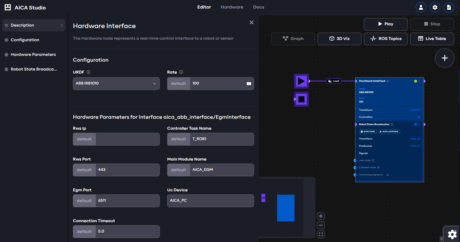
- RWS IP & port: the address and port of the RWS server, e.g. the address of the real robot or the RobotStudio device
note
OmniCore controllers and RobotWare 7.x versions by default listen on HTTPS and port 80 for RobotStudio and 443 for the real robot. If necessary, the port numbers can be modified by following the instructions in this forum post.
- EGM port: the port of the EGM server, e.g. the Remote Port Number of the UDPUC device defined in RobotStudio above
- Connection timeout: the amount of time the hardware interface tries to connect to the RWS and EGM servers before reporting an error
- Controller Task and Main Module name: Depends on the controller configuration and usually defaults to
T_ROB1andAICA_EGM, respectively. - Uc Device: The name of the UDPUC device configured above.
Before starting an application with an ABB hardware interface in AICA Studio, the motors and RAPID program on the robot must be started manually through the teach pendant or RobotStudio. After that, running the application will connect to the robot and get information about the mechanical setup of the robot being used.