FANUC manipulators
FANUC is one of the largest and most established industrial robotic manipulator manufacturers, offering advanced technology and robust performance for a wide range of automation tasks.
FANUC is one of the first major robot brands that enables accelerating Physical AI implementation through an official
first-party ROS driver in the ros2_control framework
(article from Dec 2025). This allows
advanced programming platforms like the AICA System to control the robots in real-time and deploy complex behaviors
without custom implementations.
The official driver is still under development and new functionalities are added continuously. Refer to the documentation for the latest information for hardware compatibility. The minimum robot controller software versions are:
- R-30iB Plus, R-30iB Mate Plus: V9.40P/81
- R-30iB Mini Plus: V9.40P/77
- R-50iA series: V10.10P/26
Additionally, one of the following software options are required:
- J519 Stream Motion and R912 Remote Motion
- S636 External Control Package, which includes the previous
As stated in the documentation, J568 and J570 are no longer required.
To use the FANUC collection, add the latest version of collections/fanuc to your configuration in AICA Launcher,
currently supporting the CRX-10iA and the M-10𝑖D/12. Other robot models can be added on request. Simply reach out to the
AICA support team for further information.
Connecting to a robot
The robot controllers usually provide multiple Ethernet ports. The choice of physical port is up to the user, but it has
to correspond to the port defined in the $STMO.$PHYS_PORT system variable. If you don't know how to apply the
necessary changes, contact your FANUC representative or the AICA support team.
Connect the robot with the machine that is running the AICA System and set the IP addresses such that the two devices are on the same network.
Finally, on the teach pendant, switch from TP to Auto Mode. The driver will automatically set and start the right program on the robot controller.
Hardware interface
For optimal performance, the rate of the hardware interface rate should be set according to the communication interval
of Stream Motion. For example, if the system variable $STMO.$COM_INT is set to 8 [ms], configure 125 Hertz in AICA
Studio. Depending on the robot controller being used, this value might be higher.
Returning to AICA Studio and the hardware interface, it is now possible to define the parameters and connect to the robot:
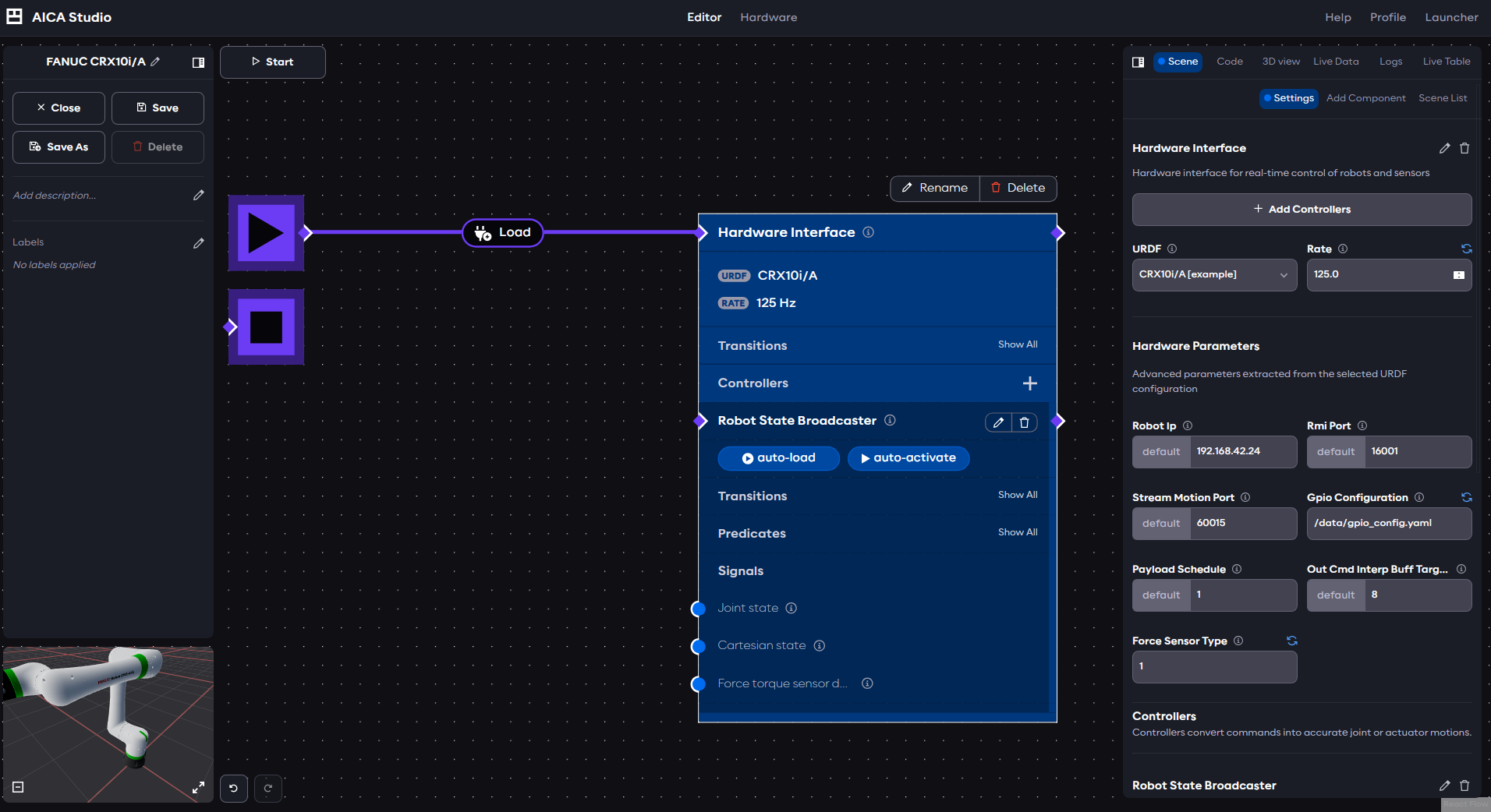
- Robot IP: the IP address of the robot
- RMI port: the port of the Remote Motion Interface (keep default unless otherwise configured on the robot controller)
- Stream Motion Port: the port of Stream Motion (keep default unless otherwise configured on the robot controller)
- GPIO configuration (v1.1.0 and above): an absolute path to a YAML file containing the GPIOs that should be configured (see more information below)
- Payload Schedule: the number of the payload to be set on the robot
- Out Cmd Interp Buff Target: Output command interpolation buffer target size for stream motion control
- Force Sensor Type (v1.1.0 and above): The type of force torque sensor to configure (see more information below)
Click Start to start the application and connect to the robot.
GPIO configuration
Selected robot controller GPIO topics support high-frequency update. The update rate is up to the robot controller sampling rate. The selection of high-frequency updated GPIOs is configured through a YAML configuration file before the driver starts. For detailed description, refer to the relevant sections in the official documentation.
The official documentation states the behavior as follows:
When outputs or numeric registers are added to the command section of the GPIO configuration YAML file, once the ROS 2 driver is launched those output and numeric register values in the controller will be set to false or zero.
However, the version of the driver provided by AICA takes additional care not to overwrite the value of the GPIOs on startup, and instead persists the initial value set on the robot controller.
A example configuration of a GPIO configuration file could look as follows:
gpio_topic_config:
  io_state:
    - type: DI
      start: 101
      length: 3
    - type: DO
      start: 101
      length: 1
  io_cmd:
    - type: DO
      start: 101
      length: 2
This configuration claims reads interfaces
- DI[101], DI[102], and DI[103] (
startis 101 andlengthis 3) - DO[101] (
startis 101 andlengthis 1)
and writes to interfaces
- DO[101] and DO[102] (
startis 101 andlengthis 2)
In order for this configuration to be accepted by the hardware interface, it is necessary to add matching state and
command interfaces to the ros2_control section of the URDF as follows:
  <ros2_control>
    <!-- keep existing parts of ros2_control -->
    <gpio name="DI">
      <state_interface name="101"/>
      <state_interface name="102"/>
      <state_interface name="103"/>
    </gpio>

    <gpio name="DO">
      <state_interface name="101"/>
      <command_interface name="101"/>
      <command_interface name="102"/>
    </gpio>
  </ros2_control>
Force torque sensor configuration
Starting with driver version collections/fanuc:v1.1.0 and robot controller software V9.40/P85, it is possible to read
force torque sensor values directly from the robot. The type of force sensor can be configured through the force_sensor_type
hardware parameter. Available types are:
- 0: Unselected
- 1: Embedded: for all CRX models with inbuilt sensor
- 2: External: for robots with an external FANUC force torque sensor mounted at the flange
Users without software V9.40/P85 should keep the type at 0 to be able to start the hardware interface.
When the force_sensor_type is set to 1 or 2, the URDF must include the following sensor interfaces within the ros2_control
element.
  <ros2_control>
    <!-- keep existing parts of ros2_control -->
    <sensor name="ft_sensor">
      <state_interface name="force.x"/>
      <state_interface name="force.y"/>
      <state_interface name="force.z"/>
      <state_interface name="torque.x"/>
      <state_interface name="torque.y"/>
      <state_interface name="torque.z"/>
    </sensor>
  </ros2_control>
The URDF must not include these interfaces if using collections/fanuc:v1.0.0 or if the force_sensor_type is set to 0.