Using Isaac Sim as a simulator
This guide builds directly on Using Isaac Sim as a visualizer, where we configured the first use case: using Isaac Sim to mirror robot motion for visualization.
Here, we focus on the second use case: controlling a simulated robot in Isaac Sim from an AICA application. Isaac Sim hosts the robot with full physics simulation, and AICA Studio interacts with it as if it were real hardware. The data flow is bidirectional:
- AICA Studio -> Isaac Sim: AICA Studio sends joint commands (positions, velocities, or efforts) to Isaac Sim via ROS 2.
- Isaac Sim -> AICA Studio: Isaac Sim simulates the robot's physical response and publishes the resulting joint states back to AICA Studio via ROS 2.
From AICA Studio's perspective, the simulated robot in Isaac Sim behaves like real hardware. This setup is well suited for validating and debugging control algorithms in a physics-based environment before deploying them to a physical robot.
If you are looking for a way to simply mirror your robot's state in Isaac Sim for monitoring or demonstration purposes, refer to Using Isaac Sim as a visualizer instead.
Prerequisites
Complete the Using Isaac Sim as a visualizer guide first, in particular the sections for prerequisites, scene setup, and the OmniGraph. This guide builds directly on top of those steps, and it is expected that your setup from the previous guide is working correctly before proceeding.
Setting up the OmniGraph
Start from the OmniGraph you built in the visualizer guide. To support control, keep that graph as-is and only apply the changes below.
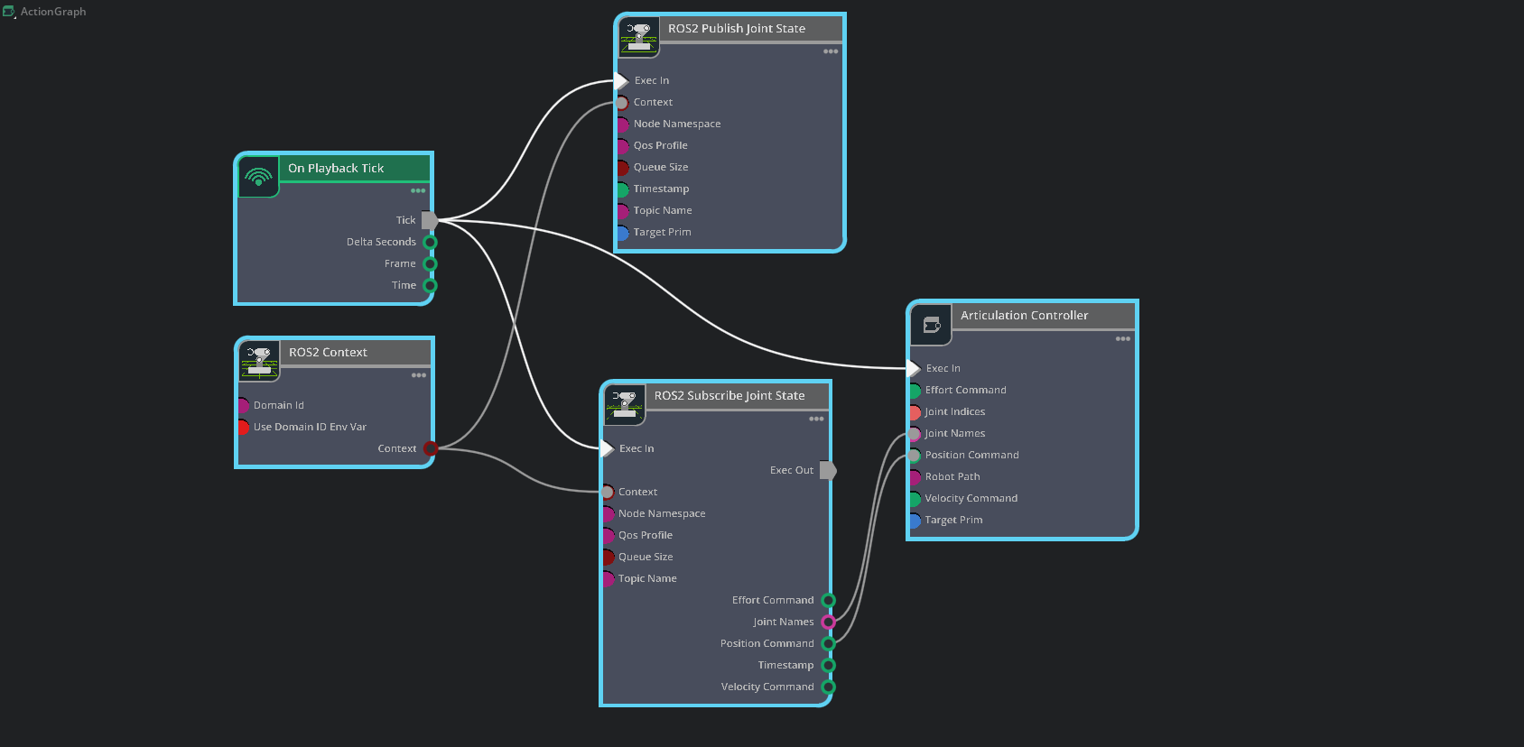
In Isaac Sim, open that existing Action Graph and add a ROS2 Publish Joint State node.
Configure only the added/updated parts:
-
ROS2 Publish Joint State:
- Set
topicNameto/joint_states - Set
targetPrimto/world/Generic/root_joint
- Set
-
ROS2 Subscribe Joint State:
- Update
topicNameto/joint_commands
- Update
-
Additional connections:
- Connect
ROS2 Context.Context->ROS2 Publish Joint State.Context - Connect
On Playback Tick.Tick->ROS2 Publish Joint State.Exec In
- Connect
All other nodes, settings, and connections remain the same as in the visualizer guide.
Your OmniGraph should look similar to the image below:
Configuring the AICA Application
On the AICA side, the key difference from the visualizer setup is the hardware interface. Instead of using a mock interface and a separate component to publish joint states, we use a topic-based ROS 2 hardware interface that communicates directly with Isaac Sim over ROS 2 topics. This interface:
- Subscribes to the
/joint_statestopic to read the simulated robot's state from Isaac Sim - Publishes to the
/joint_commandstopic to send commands to Isaac Sim
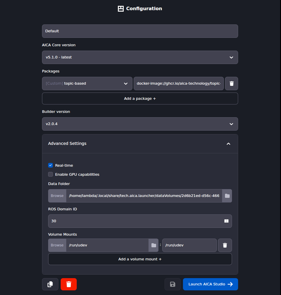
Use AICA Launcher to create a configuration that uses the latest AICA Studio version. Set the ROS 2 Domain ID to 30
to match the one configured in Isaac Sim, and include the custom community package that provides the
topic_based_ros2_control/TopicBasedSystem hardware interface plugin
ghcr.io/aica-technology/topic-based-ros2-control:v0.1.0
Your launcher configuration should look similar to the image below:
Creating a new Hardware with a Topic-Based ROS 2 Interface
First, create a new URDF in AICA Studio to communicate with Isaac Sim. This involves duplicating an existing hardware and swapping out the plugin in the URDF.
- In AICA Studio, go to the Hardware tab.
- Click on the
Generic six-axis robot armto open it and use Save As to create a copy with a new name. Name itGeneric six-axis robot arm (Topic-Based Interface). - In the URDF editor, replace the content of the URDF with the following and click Save.
Generic six-axis robot arm (Topic-Based Interface) URDF
<?xml version="1.0" ?>
<robot name="generic">
<link name="world"/>
<joint name="to_world" type="fixed">
  <parent link="world"/>
  <child link="base_link"/>
  <origin rpy="0 0 1.5708" xyz="0 0 0"/>
</joint>
<link name="base_link">
  <visual>
    <origin rpy="0 0 0" xyz="0 0 0"/>
    <geometry>
      <mesh filename="package://aica_generic_description/meshes/generic/visual/base_link.dae"/>
    </geometry>
  </visual>
</link>
<joint name="joint_1" type="revolute">
  <origin rpy="0 0 0" xyz="0 0 0.154"/>
  <parent link="base_link"/>
  <child link="link_1"/>
  <axis xyz="0 0 1"/>
  <limit effort="87.0" lower="-6.28" upper="6.28" velocity="3.14"/>
</joint>
<link name="link_1">
  <visual>
    <origin rpy="0 0 0" xyz="0 0 0"/>
    <geometry>
      <mesh filename="package://aica_generic_description/meshes/generic/visual/link_1.dae"/>
    </geometry>
  </visual>
</link>
<joint name="joint_2" type="revolute">
  <origin rpy="0 0 0" xyz="0 0 0"/>
  <parent link="link_1"/>
  <child link="link_2"/>
  <axis xyz="1 0 0"/>
  <limit effort="87.0" lower="-6.28" upper="6.28" velocity="3.14"/>
</joint>
<link name="link_2">
  <visual>
    <origin rpy="0 0 0" xyz="0 0 0"/>
    <geometry>
      <mesh filename="package://aica_generic_description/meshes/generic/visual/link_2.dae"/>
    </geometry>
  </visual>
</link>
<joint name="joint_3" type="revolute">
  <origin rpy="0 0 0" xyz="0 0 0.436"/>
  <parent link="link_2"/>
  <child link="link_3"/>
  <axis xyz="1 0 0"/>
  <limit effort="87.0" lower="-6.28" upper="6.28" velocity="3.14"/>
</joint>
<link name="link_3">
  <visual>
    <origin rpy="0 0 0" xyz="0 0 0"/>
    <geometry>
      <mesh filename="package://aica_generic_description/meshes/generic/visual/link_3.dae"/>
    </geometry>
  </visual>
</link>
<joint name="joint_4" type="revolute">
  <origin rpy="0 0 0" xyz="0.113 -0.406 0"/>
  <parent link="link_3"/>
  <child link="link_4"/>
  <axis xyz="1 0 0"/>
  <limit effort="12.0" lower="-6.28" upper="6.28" velocity="3.14"/>
</joint>
<link name="link_4">
  <visual>
    <origin rpy="0 0 0" xyz="0 0 0"/>
    <geometry>
      <mesh filename="package://aica_generic_description/meshes/generic/visual/link_4.dae"/>
    </geometry>
  </visual>
</link>
<joint name="joint_5" type="revolute">
  <origin rpy="0 0 0" xyz="0 -0.099 0"/>
  <parent link="link_4"/>
  <child link="link_5"/>
  <axis xyz="0 -1 0"/>
  <limit effort="12.0" lower="-6.28" upper="6.28" velocity="3.14"/>
</joint>
<link name="link_5">
  <visual>
    <origin rpy="0 0 0" xyz="0 0 0"/>
    <geometry>
      <mesh filename="package://aica_generic_description/meshes/generic/visual/link_5.dae"/>
    </geometry>
  </visual>
</link>
<joint name="joint_6" type="revolute">
  <origin rpy="0 0 0" xyz="0 0 -0.105"/>
  <parent link="link_5"/>
  <child link="link_6"/>
  <axis xyz="0 0 1"/>
  <limit effort="12.0" lower="-6.28" upper="6.28" velocity="3.14"/>
</joint>
<link name="link_6">
  <visual>
    <origin rpy="0 0 0" xyz="0 0 0"/>
    <geometry>
      <mesh filename="package://aica_generic_description/meshes/generic/visual/link_6.dae"/>
    </geometry>
  </visual>
</link>
<joint name="link_6-tool0" type="fixed">
  <parent link="link_6"/>
  <child link="tool0"/>
  <origin rpy="3.1416 0 -1.5708" xyz="0 0 0"/>
</joint>
<link name="tool0"/>
<ros2_control name="TopicBasedSystem" type="system">
  <hardware>
    <plugin>topic_based_ros2_control/TopicBasedSystem</plugin>
    <param name="joint_states_topic">/joint_states</param>
    <param name="joint_commands_topic">/joint_commands</param>
  </hardware>
  <joint name="joint_1">
    <command_interface name="position">
      <param name="min">-6.28</param>
      <param name="max">6.28</param>
    </command_interface>
    <command_interface name="velocity">
      <param name="min">-3.14</param>
      <param name="max">3.14</param>
    </command_interface>
    <command_interface name="effort">
      <param name="min">-87</param>
      <param name="max">87</param>
    </command_interface>
    <state_interface name="position">
      <param name="initial_value">0.0</param>
    </state_interface>
    <state_interface name="velocity" />
    <state_interface name="effort" />
  </joint>
  <joint name="joint_2">
    <command_interface name="position">
      <param name="min">-6.28</param>
      <param name="max">6.28</param>
    </command_interface>
    <command_interface name="velocity">
      <param name="min">-3.14</param>
      <param name="max">3.14</param>
    </command_interface>
    <command_interface name="effort">
      <param name="min">-87</param>
      <param name="max">87</param>
    </command_interface>
    <state_interface name="position">
      <param name="initial_value">0.0</param>
    </state_interface>
    <state_interface name="velocity" />
    <state_interface name="effort" />
  </joint>
  <joint name="joint_3">
    <command_interface name="position">
      <param name="min">-6.28</param>
      <param name="max">6.28</param>
    </command_interface>
    <command_interface name="velocity">
      <param name="min">-3.14</param>
      <param name="max">3.14</param>
    </command_interface>
    <command_interface name="effort">
      <param name="min">-87</param>
      <param name="max">87</param>
    </command_interface>
    <state_interface name="position">
      <param name="initial_value">0</param>
    </state_interface>
    <state_interface name="velocity" />
    <state_interface name="effort" />
  </joint>
  <joint name="joint_4">
    <command_interface name="position">
      <param name="min">-6.28</param>
      <param name="max">6.28</param>
    </command_interface>
    <command_interface name="velocity">
      <param name="min">-3.14</param>
      <param name="max">3.14</param>
    </command_interface>
    <command_interface name="effort">
      <param name="min">-12</param>
      <param name="max">12</param>
    </command_interface>
    <state_interface name="position">
      <param name="initial_value">0.0</param>
    </state_interface>
    <state_interface name="velocity" />
    <state_interface name="effort" />
  </joint>
  <joint name="joint_5">
    <command_interface name="position">
      <param name="min">-6.28</param>
      <param name="max">6.28</param>
    </command_interface>
    <command_interface name="velocity">
      <param name="min">-3.14</param>
      <param name="max">3.14</param>
    </command_interface>
    <command_interface name="effort">
      <param name="min">-12</param>
      <param name="max">12</param>
    </command_interface>
    <state_interface name="position">
      <param name="initial_value">0.0</param>
    </state_interface>
    <state_interface name="velocity" />
    <state_interface name="effort" />
  </joint>
  <joint name="joint_6">
    <command_interface name="position">
      <param name="min">-6.28</param>
      <param name="max">6.28</param>
    </command_interface>
    <command_interface name="velocity">
      <param name="min">-3.14</param>
      <param name="max">3.14</param>
    </command_interface>
    <command_interface name="effort">
      <param name="min">-12</param>
      <param name="max">12</param>
    </command_interface>
    <state_interface name="position">
      <param name="initial_value">0.0</param>
    </state_interface>
    <state_interface name="velocity" />
    <state_interface name="effort" />
  </joint>
</ros2_control>
</robot>
In this URDF, we define a ros2_control hardware interface that uses the topic_based_ros2_control/TopicBasedSystem
plugin. This plugin is parameterized with the names of the ROS 2 topics to subscribe to for joint states and publish to
for joint commands as shown in the highlighted lines below:
  <ros2_control name="TopicBasedSystem" type="system">
    <hardware>
      <plugin>topic_based_ros2_control/TopicBasedSystem</plugin>
      <param name="joint_states_topic">/joint_states</param>
      <param name="joint_commands_topic">/joint_commands</param>
    </hardware>
    ...
  </ros2_control>
In fact, this is the only modification required in the Generic six-axis robot arm URDF. By replacing the hardware plugin
aica_core_interfaces/MockInterface with topic_based_ros2_control/TopicBasedSystem and properly configuring the topic
names, the hardware interface is converted from a mock implementation, used solely for state simulation, into an
interface that communicates with Isaac Sim via ROS 2.
The topic names configured in the URDF must match those set in the OmniGraph nodes in Isaac Sim. The hardware interface
subscribes to /joint_states (published by the ROS2 Publish Joint State node) and publishes to /joint_commands
(consumed by the ROS2 Subscribe Joint State node).
Creating the application
Copy the YAML content below into a new application in AICA Studio and save it. This application uses the Joint
Trajectory Controller to move the Generic robot between three waypoints.
Joint Trajectory Control application
schema: 2-0-6
dependencies:
  core: v5.1.0
frames:
  wp1:
    reference_frame: world
    position:
      x: 0.492159
      y: -0.020903
      z: 0.487698
    orientation:
      w: 0
      x: -0.707107
      y: 0.707107
      z: 0.000563
  wp2:
    reference_frame: world
    position:
      x: 0.492038
      y: 0.1335
      z: 0.336067
    orientation:
      w: 0.007248
      x: 0.70707
      y: -0.707064
      z: -0.007811
  wp3:
    reference_frame: world
    position:
      x: 0.491953
      y: 0.359307
      z: 0.229181
    orientation:
      w: 0
      x: -0.707107
      y: 0.707107
      z: 0.000563
on_start:
  load:
    - hardware: hardware
hardware:
  hardware:
    display_name: Hardware Interface
    urdf: Generic six-axis robot arm (Topic-Based Interface)
    rate: 100
    events:
      transitions:
        on_load:
          load:
            - controller: robot_state_broadcaster
              hardware: hardware
            - controller: joint_trajectory_controller
              hardware: hardware
    controllers:
      robot_state_broadcaster:
        plugin: aica_core_controllers/RobotStateBroadcaster
        outputs:
          joint_state: /hardware/robot_state_broadcaster/joint_state
        events:
          transitions:
            on_load:
              switch_controllers:
                hardware: hardware
                activate: robot_state_broadcaster
        display_name: Robot State Broadcaster
      joint_trajectory_controller:
        plugin: aica_core_controllers/trajectory/JointTrajectoryController
        events:
          transitions:
            on_load:
              switch_controllers:
                hardware: hardware
                activate: joint_trajectory_controller
          predicates:
            has_trajectory_succeeded:
              call_service:
                controller: joint_trajectory_controller
                hardware: hardware
                service: set_trajectory
                payload: '{"times_from_start": [5, 7, 8], "frames": [wp1, wp2, wp3]}'
graph:
  positions:
    buttons:
      button:
        x: 360
        y: 780
    hardware:
      hardware:
        x: 1060
        y: 0
  buttons:
    button:
      display_name: Trigger Events Button
      on_click:
        call_service:
          controller: joint_trajectory_controller
          hardware: hardware
          service: set_trajectory
          payload: '{"times_from_start": [5, 7, 8], "frames": [wp1, wp2, wp3]}'
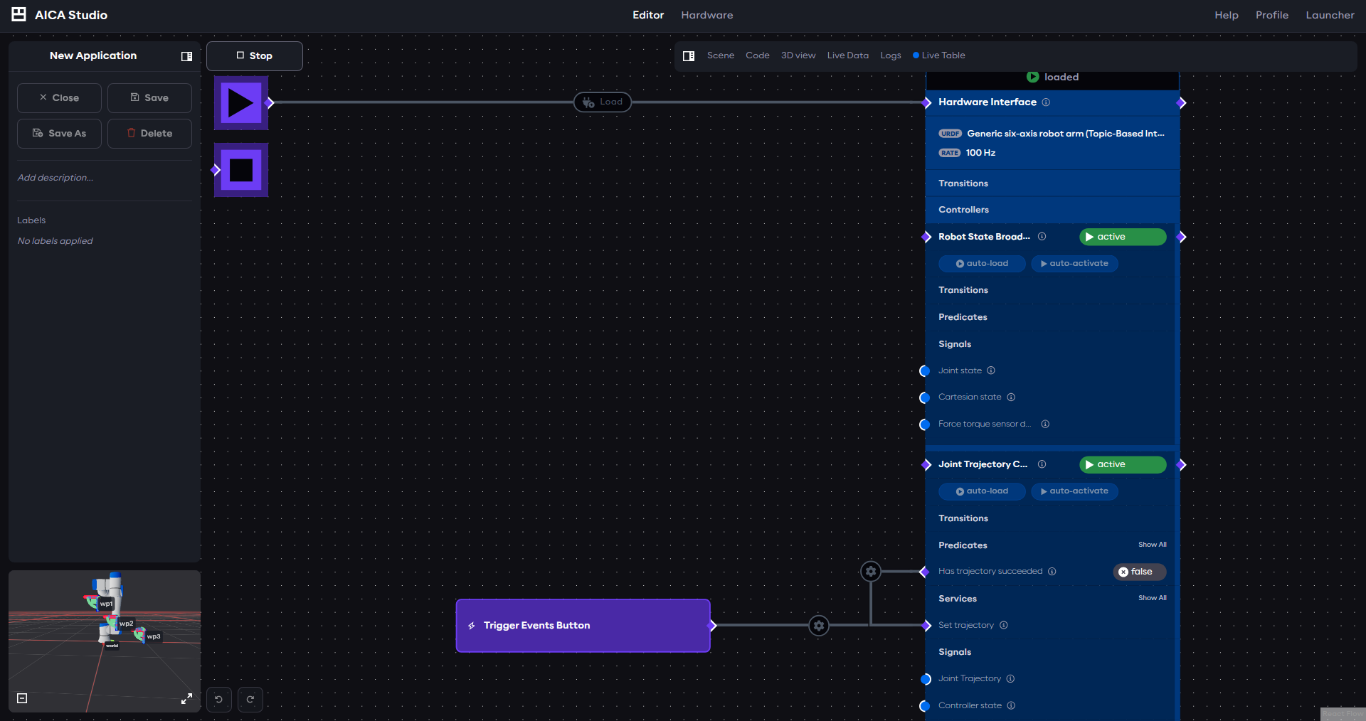
Notice that, unlike the visualizer guide's application, this one does not include a JointSignalToJointStateMsg
component. There is no need to convert and publish joint states, the topic-based hardware interface handles all
communication with Isaac Sim directly through the configured ROS 2 topics.
Your application should look similar to the image below:
Interfacing Isaac Sim with AICA Studio
With both Isaac Sim and AICA Studio configured, you can run the full simulation loop:
-
Start the AICA application: Press the
Startbutton in AICA Studio. The application will begin sending joint commands to the/joint_commandstopic and reading joint states from the/joint_statestopic. -
Start Isaac Sim: Press the
Playbutton in Isaac Sim. The OmniGraph will begin executing: it subscribes to commands from AICA, applies them to the simulated robot, and publishes the resulting joint states back.
You should see the Generic robot in Isaac Sim moving between the three waypoints defined in the application. Unlike
the visualizer setup, the robot's motion is driven by actual physics simulation; AICA Studio is sending commands
directly to the simulated robot, and Isaac Sim is computing the physical response in real time rather than simply
mirroring state from a mock interface.
If the robot does not move or behaves unexpectedly, verify the following:
- The ROS 2 Domain ID is the same in both Isaac Sim (ROS2 Context node) and AICA Studio (Launcher configuration).
- The topic names match:
/joint_statesfor state and/joint_commandsfor commands. - The
Genericrobot is selected as the target in both theROS2 Publish Joint StateandArticulation Controllernodes. - The hardware rate in AICA Studio matches the simulation tick rate in Isaac Sim.