Using Isaac Lab as a simulator
This guide establishes a workflow for developing, testing, and deploying robotic applications by using Isaac Lab as the simulation backend in the AICA System. This connection provides several key benefits:
-
RL Policy Testing: AICA’s RL Policy Component SDK allows developers to deploy Reinforcement Learning (RL) models directly onto real hardware through components in AICA Studio. These models can be trained in Isaac Lab, and with the AICA System interacting directly with Isaac Lab, users can validate trained policies under the same conditions in which they were learned.
-
Physics-Based Evaluation: Running the AICA System within a physics-based simulation such as Isaac Lab allows developers to observe how control algorithms respond to realistic dynamics, friction, collisions, and sensor noise. This ensures that behaviors tested in simulation mirror real-world performance, reducing the risk of unexpected failures during deployment and enabling safer, more reliable policy tuning before engaging with physical robots.
-
Digital Twin Control: Beyond RL, running the AICA System with Isaac Lab provides users with ways to interact with digital twins of their robots. Applications can be authored, tested, and validated entirely in simulation before connecting to actual hardware. This improves safety and enables rapid iteration in early stages, helping streamline the overall development cycle.
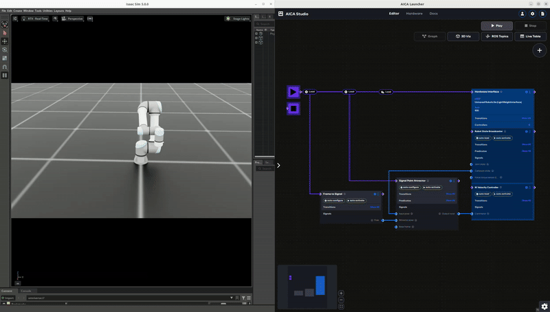
With Isaac Lab as simulator, users can build scenes in Isaac Lab, command simulated robots using AICA System, validate performance, switch the hardware interface to a real robot, and hit play with no code changes required. In the sections below, we review the steps to run the Point Attractor example with a UR5e robot simulated in Isaac Lab:
- Installing Isaac Lab: Install and test AICA Bridge in Isaac Lab
- Creating a new scene in Isaac Lab: Define and register a scene configuration class. This scene will include the robot model and any other objects it could interact with in the environment.
- Running the Isaac Lab Simulator: Launch the simulator with the desired combination of scene, rate, and other parameters.
- Configuring the AICA Application: Set up a custom hardware in AICA Studio that can communicate with the simulator.
- Running the example: Start the simulator and the AICA application to control the robot.
Complete the Point Attractor application from this page before proceeding, as this guide builds on that example.
Installing Isaac Lab
Begin by cloning AICA's fork of Isaac Lab.
Once you’ve cloned the repository, check out the v0.1.0 tag, then build and start the Docker container by running:
python3 docker/container.py start
Next, enter the running container using:
python3 docker/container.py enter
This ensures you are inside a development environment where Isaac Lab and all required dependencies are already installed. Run the following command in the same terminal to verify the installation:
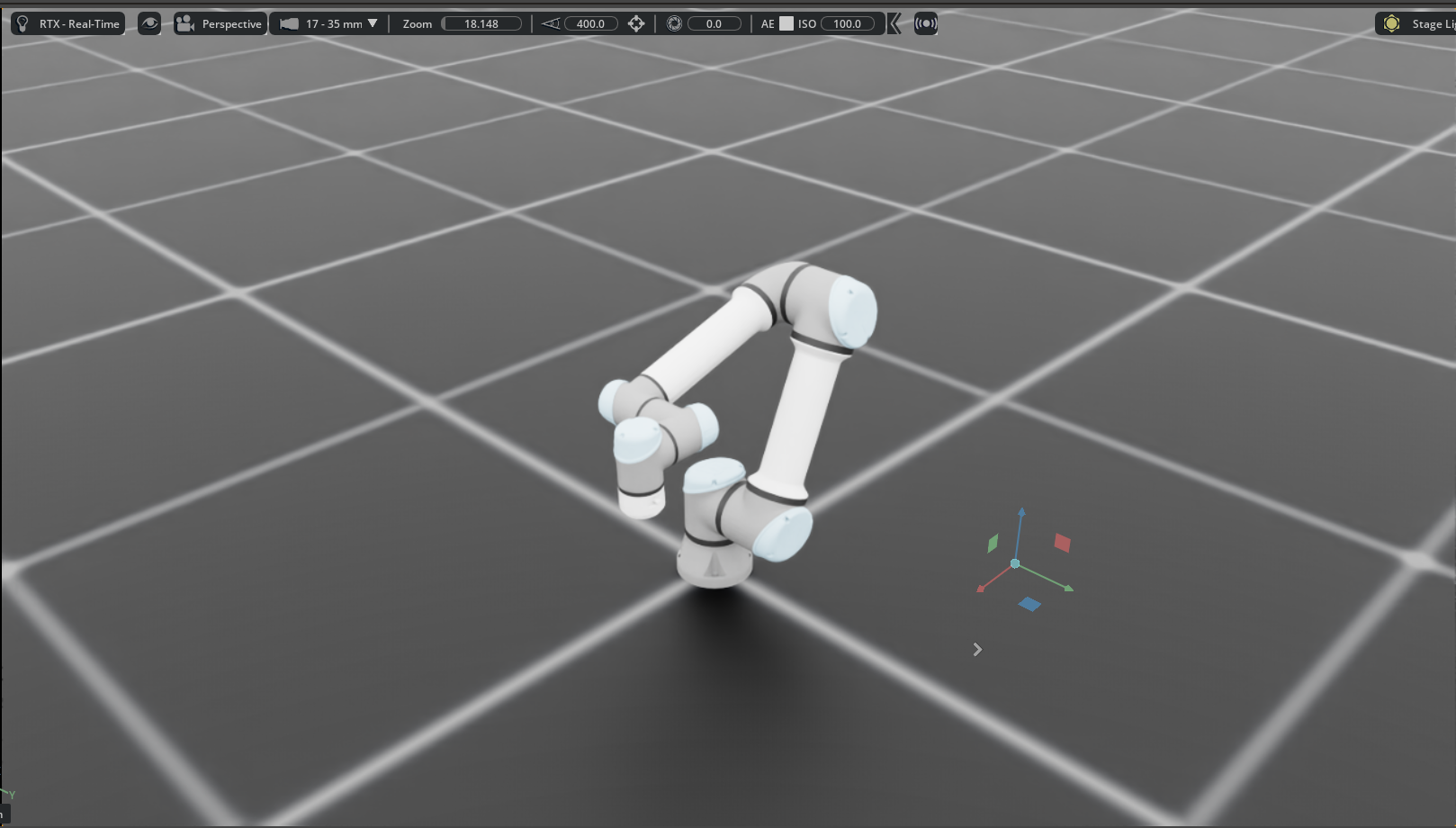
python3 scripts/custom/aica_bridge/run_bridge.py --scene basic_scene
This will spawn a UR5e robot, a ground plane, and lights. If you see the UR5e robot in the scene as shown in the image below, then the installation was successful and you are ready to proceed with the next steps. If not, carefully go over the instructions again or reach out to AICA for help.
Creating a new scene in Isaac Lab
A scene is a collection of entities (e.g., terrain, articulations, sensors, lights, etc.) that can be added to the simulation. Refer to Isaac Lab documentation on scenes for more details.
To create a new scene, you should define a scene configuration class that inherits from InteractiveSceneCfg. Various
examples of scene config classes can be found in the
scenes
directory of the Isaac Lab repository.
Scenes live entirely in Isaac Lab and the definitions of the assets used in the scene should also be defined there. By default, the 3D visualization in AICA Studio will only display the robot and mirror the robot's movements. Advanced users may export the scene from Isaac Lab as URDF and install it within AICA System to visualize the entire scene.
Once you've defined your scene configuration class, register it by adding a corresponding key to the scenes dictionary
located in
this file.
After registering the scene, you can launch it by running the following command in the development environment:
python3 scripts/custom/aica_bridge/run_bridge.py --scene <your_scene_name>
In this example we will run the basic_scene scene, which is already registered in the scenes dictionary.
Running the Isaac Lab Simulator
The simulator provides a list of parameters that you should understand before configuring it:
Some of these parameters have counterparts defined in the hardware interface used within AICA Studio and will be introduced below.
- scene: Specifies which scene to load in the simulator.
- rate: Sets the simulation update frequency in hertz (Hz). The default is 100 Hz, but you can adjust this value based on your application’s requirements.
- ft_sensor_name: If provided, a sensor will be attached to the end-effector link.
caution
If a
<sensor>plugin in the URDF of the hardware interface used in AICA Studio is configured, the name of the sensor here needs to correspond to the name of the sensor in the URDF. - ip_address: Indicates the IP address of the machine running AICA Core. If the simulator and AICA Core are on the
same network, keep the default
*. - state_port: The port used to stream state updates from the simulator to the hardware interface in AICA Studio. The
default is 1801, and it must match the
state_portspecified in the hardware interface configuration. - command_port: The port used to stream commands from the hardware interface in AICA Studio to the simulator. The
default is 1802, and it must match the
command_portin the hardware interface configuration. - ft_sensor_port: The port used to stream force/torque measurements from the simulator to the hardware interface in
AICA Studio. The default is 1803, and it must match the
ft_sensor_portin the hardware interface configuration. - joint_names: Lists the joint names that will be controlled through AICA Studio. For example, if you are using a
Franka Panda robot with a gripper but only want to control the arm, you can specify:
panda_joint1, panda_joint2, panda_joint3, panda_joint4, panda_joint5, panda_joint6, panda_joint7. The simulator will then only send states and accept commands for those joints. If you want to control all joints, you can keep the default.*. - command_interface: Defines the command type accepted by the simulator. The default is
positions, but you can set it tovelocitiesortorquesas needed. The choice of command type depends on the controller used in AICA Studio. If a mismatched command type is received, the simulator will stop with aValueError. - headless: When set to
true, runs the simulator in headless mode (e.g. without opening user interface), useful for remote simulations or running the simulation at high frequencies. - device: Specifies the compute device for the simulation. The default is
cudafor GPU acceleration, but you can switch tocpuif GPU resources are unavailable.
Ensure these parameters are correctly configured to enable seamless communication between the simulator and your AICA
application. In case you want to run the simulator with different parameters, you can do so by running the following
command in the run_bridge.py script:
python3 scripts/custom/aica_bridge/run_bridge.py \
  --scene <your_scene_name> \
  --rate <simulation_rate> \
  --ft_sensor_name <ft_sensor_name_in_urdf> \
  --state_port <state_port> \
  --command_port <command_port> \
  --ft_sensor_port <ft_sensor_port> \
  --joint_names <comma_separated_joint_names_to_control> \
  --command_interface <positions | velocities | torques> \
  --headless <true | false> \
  --device <cuda | cpu>
Configuring the AICA Application
Using AICA Launcher, make sure that your configuration includes the collections/ur-collection package.
First, configure the hardware interface in AICA Studio to communicate with the Isaac Lab simulator. This involves duplicating an existing hardware and swap out the plugin in the URDF.
-
In AICA Studio, go to the Hardware tab.
-
Click on the
Universal Robots 5e (mock interface)to open it and use Save As to create a copy with a new name and description. For example, name itUniversal Robots 5e (LightWeightInterface)as this is the name used in the example attached below. -
Replace the content of the URDF with the following and click Save.
UR5e URDF using the
LightWeightInterface<?xml version="1.0"?>
<robot name="ur5e">
<link name="world" />
<link name="base_link" />
<link name="base_link_inertia">
<visual>
<origin rpy="0 0 3.141592653589793" xyz="0 0 0" />
<geometry>
<mesh filename="package://ur_description/meshes/ur5e/visual/base.dae" />
</geometry>
</visual>
<collision>
<origin rpy="0 0 3.141592653589793" xyz="0 0 0" />
<geometry>
<mesh filename="package://ur_description/meshes/ur5e/collision/base.stl" />
</geometry>
</collision>
<inertial>
<mass value="4.0" />
<origin rpy="0 0 0" xyz="0 0 0" />
<inertia ixx="0.00443333156" ixy="0.0" ixz="0.0" iyy="0.00443333156" iyz="0.0" izz="0.0072" />
</inertial>
</link>
<link name="shoulder_link">
<visual>
<origin rpy="0 0 3.141592653589793" xyz="0 0 0" />
<geometry>
<mesh filename="package://ur_description/meshes/ur5e/visual/shoulder.dae" />
</geometry>
</visual>
<collision>
<origin rpy="0 0 3.141592653589793" xyz="0 0 0" />
<geometry>
<mesh filename="package://ur_description/meshes/ur5e/collision/shoulder.stl" />
</geometry>
</collision>
<inertial>
<mass value="3.761" />
<origin rpy="0 0 0" xyz="0 0 0" />
<inertia ixx="0.01043677082529" ixy="0.0" ixz="0.0" iyy="0.01043677082529" iyz="0.0"
izz="0.006769799999999999" />
</inertial>
</link>
<link name="upper_arm_link">
<visual>
<origin rpy="1.5707963267948966 0 -1.5707963267948966" xyz="0 0 0.138" />
<geometry>
<mesh filename="package://ur_description/meshes/ur5e/visual/upperarm.dae" />
</geometry>
</visual>
<collision>
<origin rpy="1.5707963267948966 0 -1.5707963267948966" xyz="0 0 0.138" />
<geometry>
<mesh filename="package://ur_description/meshes/ur5e/collision/upperarm.stl" />
</geometry>
</collision>
<inertial>
<mass value="8.058" />
<origin rpy="0 1.5707963267948966 0" xyz="-0.2125 0.0 0.138" />
<inertia ixx="0.128541836083245" ixy="0.0" ixz="0.0" iyy="0.128541836083245" iyz="0.0"
izz="0.014504399999999999" />
</inertial>
</link>
<link name="forearm_link">
<visual>
<origin rpy="1.5707963267948966 0 -1.5707963267948966" xyz="0 0 0.007" />
<geometry>
<mesh filename="package://ur_description/meshes/ur5e/visual/forearm.dae" />
</geometry>
</visual>
<collision>
<origin rpy="1.5707963267948966 0 -1.5707963267948966" xyz="0 0 0.007" />
<geometry>
<mesh filename="package://ur_description/meshes/ur5e/collision/forearm.stl" />
</geometry>
</collision>
<inertial>
<mass value="2.846" />
<origin rpy="0 1.5707963267948966 0" xyz="-0.1961 0.0 0.007" />
<inertia ixx="0.03904256026963631" ixy="0.0" ixz="0.0" iyy="0.03904256026963631" iyz="0.0"
izz="0.005122799999999999" />
</inertial>
</link>
<link name="wrist_1_link">
<visual>
<origin rpy="1.5707963267948966 0 0" xyz="0 0 -0.127" />
<geometry>
<mesh filename="package://ur_description/meshes/ur5e/visual/wrist1.dae" />
</geometry>
</visual>
<collision>
<origin rpy="1.5707963267948966 0 0" xyz="0 0 -0.127" />
<geometry>
<mesh filename="package://ur_description/meshes/ur5e/collision/wrist1.stl" />
</geometry>
</collision>
<inertial>
<mass value="1.37" />
<origin rpy="0 0 0" xyz="0 0 0" />
<inertia ixx="0.0028769988492000002" ixy="0.0" ixz="0.0" iyy="0.0028769988492000002" iyz="0.0"
izz="0.0024660000000000003" />
</inertial>
</link>
<link name="wrist_2_link">
<visual>
<origin rpy="0 0 0" xyz="0 0 -0.0997" />
<geometry>
<mesh filename="package://ur_description/meshes/ur5e/visual/wrist2.dae" />
</geometry>
</visual>
<collision>
<origin rpy="0 0 0" xyz="0 0 -0.0997" />
<geometry>
<mesh filename="package://ur_description/meshes/ur5e/collision/wrist2.stl" />
</geometry>
</collision>
<inertial>
<mass value="1.3" />
<origin rpy="0 0 0" xyz="0 0 0" />
<inertia ixx="0.002729998908" ixy="0.0" ixz="0.0" iyy="0.002729998908" iyz="0.0" izz="0.00234" />
</inertial>
</link>
<link name="wrist_3_link">
<visual>
<origin rpy="1.5707963267948966 0 0" xyz="0 0 -0.0989" />
<geometry>
<mesh filename="package://ur_description/meshes/ur5e/visual/wrist3.dae" />
</geometry>
</visual>
<collision>
<origin rpy="1.5707963267948966 0 0" xyz="0 0 -0.0989" />
<geometry>
<mesh filename="package://ur_description/meshes/ur5e/collision/wrist3.stl" />
</geometry>
</collision>
<inertial>
<mass value="0.365" />
<origin rpy="0 0 0" xyz="0.0 0.0 -0.0229" />
<inertia ixx="0.00019212345231725498" ixy="0.0" ixz="0.0" iyy="0.00019212345231725498"
iyz="0.0" izz="0.000256640625" />
</inertial>
</link>
<joint name="base_joint" type="fixed">
<origin rpy="0 0 0" xyz="0 0 0" />
<parent link="world" />
<child link="base_link" />
</joint>
<joint name="base_link-base_link_inertia" type="fixed">
<parent link="base_link" />
<child link="base_link_inertia" />
<origin rpy="0 0 3.141592653589793" xyz="0 0 0" />
</joint>
<joint name="shoulder_pan_joint" type="revolute">
<parent link="base_link_inertia" />
<child link="shoulder_link" />
<origin rpy="0 0 0" xyz="0 0 0.1625" />
<axis xyz="0 0 1" />
<limit effort="150.0" lower="-6.283185307179586" upper="6.283185307179586"
velocity="3.141592653589793" />
<dynamics damping="0" friction="0" />
</joint>
<joint name="shoulder_lift_joint" type="revolute">
<parent link="shoulder_link" />
<child link="upper_arm_link" />
<origin rpy="1.570796327 0 0" xyz="0 0 0" />
<axis xyz="0 0 1" />
<limit effort="150.0" lower="-6.283185307179586" upper="6.283185307179586"
velocity="3.141592653589793" />
<dynamics damping="0" friction="0" />
</joint>
<joint name="elbow_joint" type="revolute">
<parent link="upper_arm_link" />
<child link="forearm_link" />
<origin rpy="0 0 0" xyz="-0.425 0 0" />
<axis xyz="0 0 1" />
<limit effort="150.0" lower="-3.141592653589793" upper="3.141592653589793"
velocity="3.141592653589793" />
<dynamics damping="0" friction="0" />
</joint>
<joint name="wrist_1_joint" type="revolute">
<parent link="forearm_link" />
<child link="wrist_1_link" />
<origin rpy="0 0 0" xyz="-0.3922 0 0.1333" />
<axis xyz="0 0 1" />
<limit effort="28.0" lower="-6.283185307179586" upper="6.283185307179586"
velocity="3.141592653589793" />
<dynamics damping="0" friction="0" />
</joint>
<joint name="wrist_2_joint" type="revolute">
<parent link="wrist_1_link" />
<child link="wrist_2_link" />
<origin rpy="1.570796327 0 0" xyz="0 -0.0997 -2.044881182297852e-11" />
<axis xyz="0 0 1" />
<limit effort="28.0" lower="-6.283185307179586" upper="6.283185307179586"
velocity="3.141592653589793" />
<dynamics damping="0" friction="0" />
</joint>
<joint name="wrist_3_joint" type="revolute">
<parent link="wrist_2_link" />
<child link="wrist_3_link" />
<origin rpy="1.570796326589793 3.141592653589793 3.141592653589793"
xyz="0 0.0996 -2.042830148012698e-11" />
<axis xyz="0 0 1" />
<limit effort="28.0" lower="-6.283185307179586" upper="6.283185307179586"
velocity="3.141592653589793" />
<dynamics damping="0" friction="0" />
</joint>
<link name="base" />
<joint name="base_link-base_fixed_joint" type="fixed">
<origin rpy="0 0 3.141592653589793" xyz="0 0 0" />
<parent link="base_link" />
<child link="base" />
</joint>
<link name="flange" />
<joint name="wrist_3-flange" type="fixed">
<parent link="wrist_3_link" />
<child link="flange" />
<origin rpy="0 -1.5707963267948966 -1.5707963267948966" xyz="0 0 0" />
</joint>
<link name="tool0" />
<joint name="flange-tool0" type="fixed">
<origin rpy="1.5707963267948966 0 1.5707963267948966" xyz="0 0 0" />
<parent link="flange" />
<child link="tool0" />
</joint>
<ros2_control name="ur5e" type="system">
<hardware>
  <plugin>aica_core_interfaces/LightWeightInterface</plugin>
  <param name="ip">0.0.0.0</param>
  <param name="state_port">1801</param>
  <param name="command_port">1802</param>
  <param name="ft_sensor_port">1803</param>
  <param name="bind_state_port">False</param>
  <param name="bind_command_port">False</param>
  <param name="bind_ft_sensor_port">False</param>
</hardware>
<joint name="shoulder_pan_joint">
<command_interface name="position" />
<command_interface name="velocity" />
<state_interface name="position">
<!-- initial position for the mock system and simulation -->
<param name="initial_value">0.0</param>
</state_interface>
<state_interface name="velocity">
<param name="initial_value">0.0</param>
</state_interface>
<state_interface name="effort">
<param name="initial_value">0.0</param>
</state_interface>
</joint>
<joint name="shoulder_lift_joint">
<command_interface name="position" />
<command_interface name="velocity" />
<state_interface name="position">
<!-- initial position for the mock system and simulation -->
<param name="initial_value">-1.57</param>
</state_interface>
<state_interface name="velocity">
<param name="initial_value">0.0</param>
</state_interface>
<state_interface name="effort">
<param name="initial_value">0.0</param>
</state_interface>
</joint>
<joint name="elbow_joint">
<command_interface name="position" />
<command_interface name="velocity" />
<state_interface name="position">
<!-- initial position for the mock system and simulation -->
<param name="initial_value">0.0</param>
</state_interface>
<state_interface name="velocity">
<param name="initial_value">0.0</param>
</state_interface>
<state_interface name="effort">
<param name="initial_value">0.0</param>
</state_interface>
</joint>
<joint name="wrist_1_joint">
<command_interface name="position" />
<command_interface name="velocity" />
<state_interface name="position">
<!-- initial position for the mock system and simulation -->
<param name="initial_value">-1.57</param>
</state_interface>
<state_interface name="velocity">
<param name="initial_value">0.0</param>
</state_interface>
<state_interface name="effort">
<param name="initial_value">0.0</param>
</state_interface>
</joint>
<joint name="wrist_2_joint">
<command_interface name="position" />
<command_interface name="velocity" />
<state_interface name="position">
<!-- initial position for the mock system and simulation -->
<param name="initial_value">0.0</param>
</state_interface>
<state_interface name="velocity">
<param name="initial_value">0.0</param>
</state_interface>
<state_interface name="effort">
<param name="initial_value">0.0</param>
</state_interface>
</joint>
<joint name="wrist_3_joint">
<command_interface name="position" />
<command_interface name="velocity" />
<state_interface name="position">
<!-- initial position for the mock system and simulation -->
<param name="initial_value">0.0</param>
</state_interface>
<state_interface name="velocity">
<param name="initial_value">0.0</param>
</state_interface>
<state_interface name="effort">
<param name="initial_value">0.0</param>
</state_interface>
</joint>
</ros2_control>
</robot> -
Save your changes.
-
Inspect the content of the new robot description to find the
hardwaretag. You will notice the following content:<hardware>
<plugin>aica_core_interfaces/LightWeightInterface</plugin>
<param name="ip">0.0.0.0</param>
<param name="state_port">1801</param>
<param name="command_port">1802</param>
<param name="ft_sensor_port">1803</param>
<param name="bind_state_port">False</param>
<param name="bind_command_port">False</param>
<param name="bind_ft_sensor_port">False</param>
</hardware>The
LightWeightInterfaceplugin facilitates communication between the AICA Core and Isaac Lab. For future reference, if you plan to use your own URDF, ensure that the hardware tag is written as shown above. -
Finally, open the Point Attractor application from your database and modify the hardware interface to use the newly created
Universal Robots 5e (LightWeightInterface)hardware:Point Attractor Application
schema: 2-0-4
dependencies:
  core: v4.4.2
frames:
  target:
    reference_frame: world
    position:
      x: 0.328215
      y: 0.056976
      z: 0.336586
    orientation:
      w: -0.000004
      x: 1
      y: 0
      z: 0
on_start:
  load:
    - component: signal_point_attractor
    - hardware: hardware
    - component: frame_to_signal
components:
  frame_to_signal:
    component: aica_core_components::ros::TfToSignal
    display_name: Frame to Signal
    events:
      transitions:
        on_load:
          lifecycle:
            component: frame_to_signal
            transition: configure
        on_configure:
          lifecycle:
            component: frame_to_signal
            transition: activate
    parameters:
      frame: target
    outputs:
      pose: /frame_to_signal/pose
  signal_point_attractor:
    component: aica_core_components::motion::SignalPointAttractor
    display_name: Signal Point Attractor
    events:
      transitions:
        on_load:
          lifecycle:
            component: signal_point_attractor
            transition: configure
        on_configure:
          lifecycle:
            component: signal_point_attractor
            transition: activate
    inputs:
      state: /hardware/robot_state_broadcaster/cartesian_state
      attractor: /frame_to_signal/pose
    outputs:
      twist: /signal_point_attractor/twist
hardware:
  hardware:
    display_name: Hardware Interface
    urdf: Universal Robots 5e (LightWeightInterface)
    rate: 100
    events:
      transitions:
        on_load:
          load:
            - controller: robot_state_broadcaster
              hardware: hardware
            - controller: ik_velocity_controller
              hardware: hardware
    controllers:
      robot_state_broadcaster:
        plugin: aica_core_controllers/RobotStateBroadcaster
        outputs:
          cartesian_state: /hardware/robot_state_broadcaster/cartesian_state
        events:
          transitions:
            on_load:
              switch_controllers:
                hardware: hardware
                activate: robot_state_broadcaster
      ik_velocity_controller:
        plugin: aica_core_controllers/velocity/IKVelocityController
        inputs:
          command: /signal_point_attractor/twist
        events:
          transitions:
            on_load:
              switch_controllers:
                hardware: hardware
                activate: ik_velocity_controller
graph:
  positions:
    components:
      frame_to_signal:
        x: 200
        y: 600
      signal_point_attractor:
        x: 660
        y: 520
    hardware:
      hardware:
        x: 1120
        y: -20
  edges:
    on_start_on_start_signal_point_attractor_signal_point_attractor:
      path:
        - x: 380
          y: 40
        - x: 380
          y: 580
    on_start_on_start_frame_to_signal_frame_to_signal:
      path:
        - x: 140
          y: 40
        - x: 140
          y: 660
    hardware_hardware_robot_state_broadcaster_cartesian_state_signal_point_attractor_state:
      path:
        - x: 620
          y: 520
        - x: 620
          y: 780
Running the example
All the pieces to to run this example are now in place.
Launch the simulator inside the Isaac Lab development environment Docker container using:
python3 scripts/custom/aica_bridge/run_bridge.py --scene basic_scene --command_interface velocities
Then, play your AICA application from the previous step. Go to the 3D view and drag the command frame around to move
the robot in space.
Beware
When running the AICA System and Isaac Lab simulator, there are several important points to keep in mind to ensure safe and reliable performance:
- Robot joint names: Ensure that the joint names in the URDF of AICA Studio match those expected by the USD file in Isaac Lab. In the current implementation, there are two sources of truth for joint names: the URDF file and USD file. If these names don't match, the simulator will not be able to send the states correctly to the AICA application.
- Simulation Rate: The simulation rate in Isaac Lab should be set to a value that allows for smooth and realistic updates. Commands are updated at the simulation rate, so if the rate is too low, then the robot may not respond as expected.
- Hardware interface rate in AICA Studio: The hardware interface rate in AICA Studio should match the simulation rate set in Isaac Lab.
- Force Sensor: If a force torque sensor is configured in the URDF of AICA Studio, ensure that the simulator is
configured to provide force-torque data. This is done by setting the
ft_sensor_nameparameter to the name of the force torque sensor present in the URDF. - Command Interface: Ensure that the command interface in the simulator matches the type of commands being sent by the controllers in AICA Studio.