A guide on joint trajectory workflows
In our concepts page for the Joint Trajectory Controller (JTC) we already covered why trajectory controllers are often needed in robotics. In short, executing trajectories, in joint or Cartesian space, is often a fundamental piece of a robotics application workflow. Whether you need to address pick and place tasks, or simply move through predetermined locations, you are in need of a controller that is able to traverse space accurately and timely.
While we cover the basics of JTC in a separate example, here we will focus more on its integration with AICA Studio and suggest workflows and/or parametrizations that might aid you when building big applications.
Visit our learning platform AICAdemy for an interactive training module with a real robot on this topic:
Setting up your environment
JTC has a plethora of parameters that can be set to alter its performance according to an application's requirements. Let us start by creating a new application that we can use as a reference point for this guide.
First, start AICA Launcher and create a configuration with AICA Core v4.4.2 or higher. For the remainder of this guide, we will be using the generic six-axis robot that is part of our core hardware collection. However, if you have the appropriate entitlements and want to experiment with a different robot brand, feel free to add the corresponding collection to your configuration before launching it.
Configuring your hardware interface
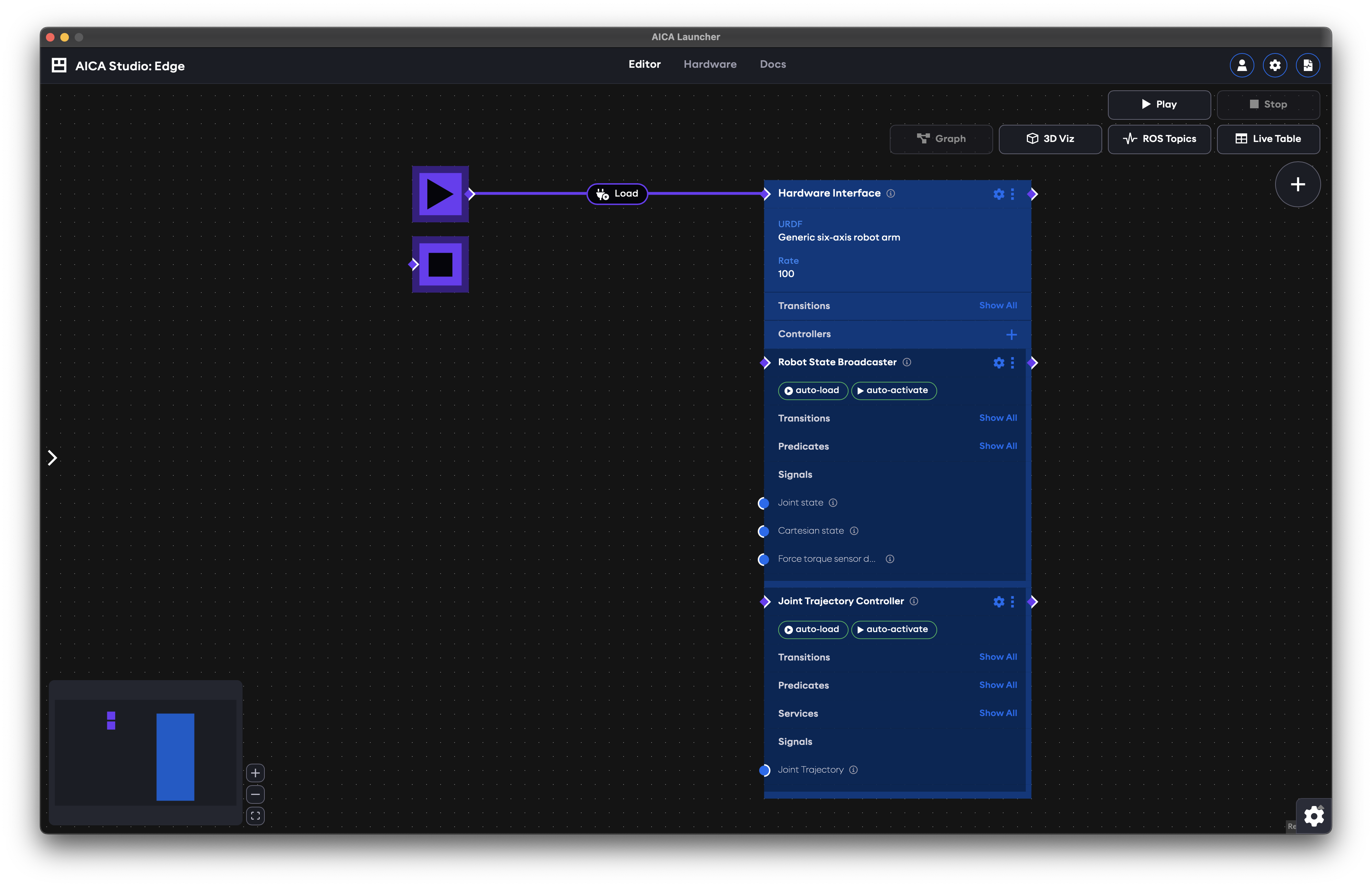
Create a new application and:
- Open the settings menu of the hardware interface and set the URDF to
Generic six-axis robot arm, then proceed to close this menu. - Add a
Joint Trajectory Controllerto the hardware interface and set it to:- auto-load
- auto-activate
- Connect the start block to the hardware interface to load it on start.
Your application should look like this:
Parametrizing JTC
Click on the small gear icon on the Joint Trajectory Controller block we just added to view and edit the available
parameters.
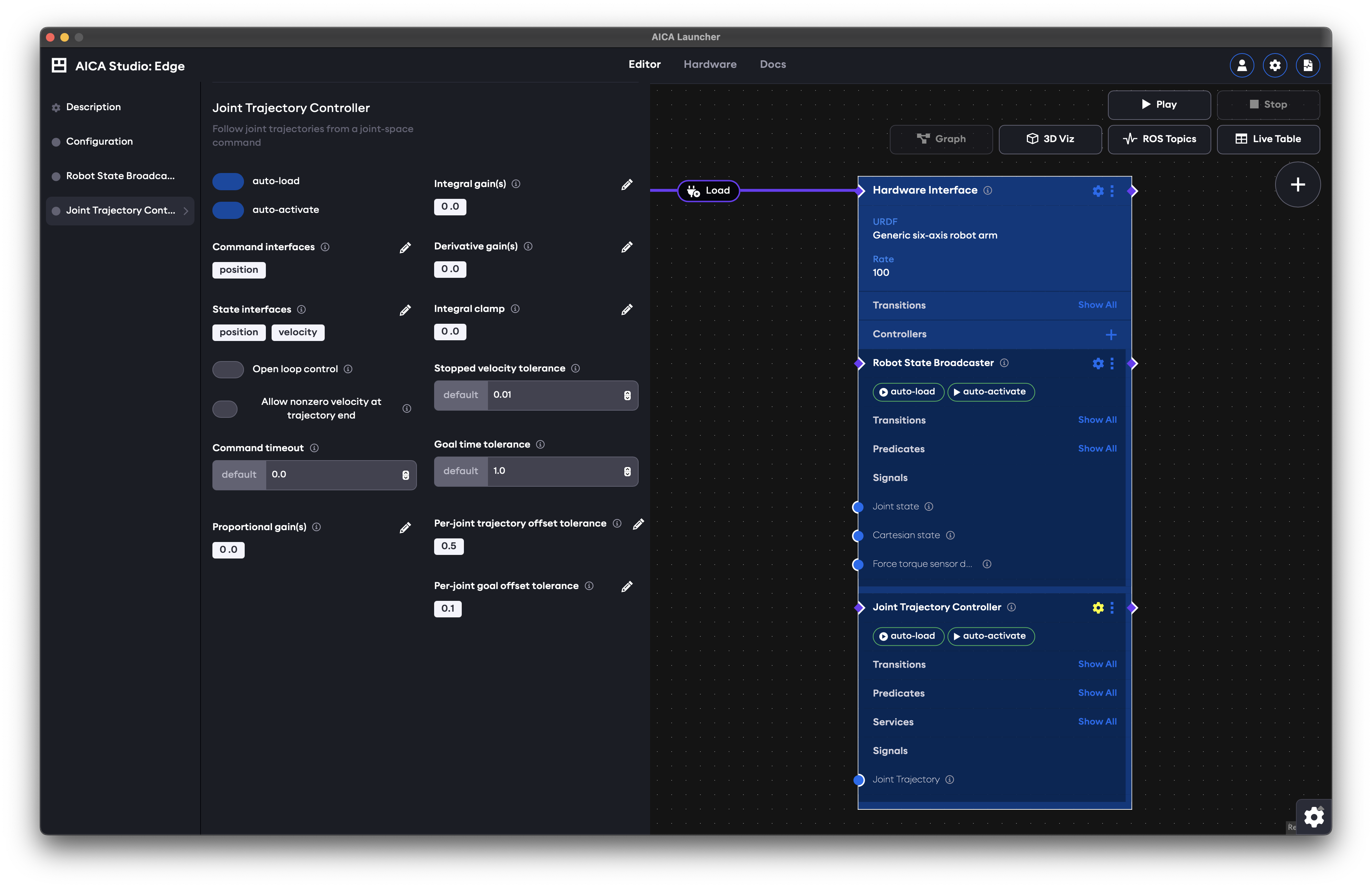
Let us cover some of these parameters:
Command interfaces: that refers to the type of command that JTC will use to control your robot; one of position, velocity, acceleration, or effort.State interfaces: the type of state interfaces JTC will claim. Some interfaces may be necessary depending on your choice of command interfaces. For example, if you want to control your robot in acceleration, you need to have a velocity state interface.Open loop control: refers to whether the controller will be correcting its desired commands according to the state it is receiving or not.Allow nonzero velocity at trajectory end: typically, you want the robot to halt when it reaches the end of your trajectory. However, there are cases, e.g., when you are controlling in velocities, where you want to allow non-zero values even if the trajectory waypoints have been successfully traversed.Proportional/Integral/Derivative gain(s): these gains are to be set and tuned when you are, for example, commanding in velocity but your trajectory has positions. Then, a PID control will be applied to generate desired velocities through the trajectory.
You will also notice tolerance values for trajectory execution times and position offsets. These should be set on a per-application basis, as failing to satisfy the corresponding constraints would lead to the trajectory failing mid-execution.
You may find advanced parameters in the Docs tab under the Joint Trajectory Controller page. These parameters can be
used to further tune JTC's performance and functionality, but may also require more advanced knowledge in order to tune
them. Make sure to carefully read the descriptions next to each parameter before making changes.
Setting a trajectory for execution
There are 2 ways of setting a trajectory in JTC:
- by using a
JointTrajectorysignal - by calling the
set_trajectoryservice
In both cases, receiving a new joint trajectory will first trigger cancellation of an active trajectory, if there is one. That is, there is no trajectory buffering or appending taking place. As with many things in the AICA Universe, behaviors are event-driven. If you wish to send multiple trajectories back-to-back, you will have to rely on the execution status of the active trajectory handled by JTC. There is a practical example of how do this in following sections (see Putting an application together).
Trajectory execution status
The controller exposes 4 predicates to reflect the the execution status of a trajectory, namely:
Has active trajectory: A trajectory has been set and is being executedHas trajectory succeeded: A trajectory was executed successfully (i.e., reached the final waypoint within all tolerances)Has trajectory failed: A trajectory failed to execute because a tolerance was violated (i.e., desired waypoint was not reached and/or time duration was exceeded)Is trajectory cancelled: A user-triggered request to cancel the trajectory was successfully processed
Using JTC with signals
In practice, this requires publishing a single
JointTrajectory message. In AICA
Studio terms, that means connecting an edge from a custom component directly to the input of JTC. If you already have a
component that has the corresponding signal output, feel free to skip the next segment.
If you are writing the signal logic yourself, the following code indicates what your message-related code may look like:
- Python
- C++
import rclpy
from trajectory_msgs.msg import JointTrajectory, JointTrajectoryPoint

# Typically in your constructor
self._trajectory = JointTrajectory()
self.add_output("trajectory", "_trajectory", JointTrajectory, publish_on_step=False)

# Typically in a conditional block that will write the output upon the success of some criteria
self._trajectory.header.stamp = self.get_clock().now().to_msg()
self._trajectory.joint_names = ['joint_0', 'joint_1', 'joint_2', 'joint_3', 'joint_4', 'joint_5']

p1 = JointTrajectoryPoint()
p1.positions = [0.6, 0.2, 0.0, 0.0, -0.2, 0.0]
p1.velocities = [0.0, 0.0, 0.0, 0.0, 0.0, 0.0]
p1.time_from_start = rclpy.time.Duration(seconds=2.0).to_msg()

p2 = JointTrajectoryPoint()
p2.positions = [-0.6, -0.2, 0.0, 0.0, 0.2, 0.0]
p2.velocities = [0.0, 0.0, 0.0, 0.0, 0.0, 0.0]
p2.time_from_start = rclpy.time.Duration(seconds=4.0).to_msg()

self._trajectory.points = [p1, p2]

self.publish_output("trajectory")
#pragma once

#include <trajectory_msgs/msg/joint_trajectory.hpp>
#include <trajectory_msgs/msg/joint_trajectory_point.hpp>

// typically in your header, define a member variable for the trajectory
std::shared_ptr<trajectory_msgs::msg::JointTrajectory> trajectory_;
#include "custom_component_package/CppComponent.hpp"

// Typically in your constructor
this->trajectory_ = std::make_shared<trajectory_msgs::msg::JointTrajectory>();
this->add_output("trajectory", this->trajectory_, "", false, false);

// Typically in a conditional block that will write the output upon the success of some criteria
this->trajectory_->header.stamp = this->get_node()->get_clock()->now();
this->trajectory_->joint_names = {"joint_0", "joint_1", "joint_2", "joint_3", "joint_4", "joint_5"};
this->trajectory_->points.resize(2);

this->trajectory_->points[0].positions = {0.6, 0.2, 0.0, 0.0, -0.2, 0.0};
this->trajectory_->points[0].velocities = {0.0, 0.0, 0.0, 0.0, 0.0, 0.0};
this->trajectory_->points[0].time_from_start = rclcpp::Duration::from_seconds(2.0);

this->trajectory_->points[1].positions = {-0.6, -0.2, 0.0, 0.0, 0.2, 0.0};
this->trajectory_->points[1].velocities = {0.0, 0.0, 0.0, 0.0, 0.0, 0.0};
this->trajectory_->points[1].time_from_start = rclcpp::Duration::from_seconds(4.0);

this->publish_output("trajectory");
The joint names need to correspond to the joint names from your URDF. If you are not
using the Generic six-axis robot arm, you will need to adjust these names.
The easiest way to do so if you do not already know them is to head to the Hardware menu of your AICA Launcher and
read through your URDF.
Using JTC's Set trajectory service
The service currently accepts 6 variables, namely:
times_from_start: a list of timestamps (in seconds) measured from the start, indicating when JTC should reach each frame.durations: a list of absolute durations (in seconds) that correspond to each waypoint.frames: names of the Cartesian frames to reach with the robot end effector.joint_positions: names of joint positions that the robot should achieve.blending_factors: factors in [0.0, 1.0] indicating the amount of curving allowed between 2 consecutive waypoints. The default blending factors are all set to 0.0. The last trajectory segment is not considered in blending, therefore, the vector's size needs to be equal to the number of frames or joint positions minus 1 or simply contain a single value to be applied to all waypoints that support blending.blending_samples: the number of samples (minimum 10; default 50) to be used when generating the blended trajectory. If you find that your blended trajectory is not smooth enough, consider increasing this number.
The payload can only contain one of frames and joint_positions and either times_from_start or durations.
When frames are provided, an Inverse Kinematics (IK) solver will compute the joint positions that the robot should
reach. In the case of joint_positions, the recorded joint configurations are directly used in the joint trajectory.
When using times_from_start, the length of frames or joint_positions need to be equal to the times provided and
each value corresponds to exactly one waypoint. Similarly, durations can have the same length as your waypoints vector,
or be expressed as a single-element vector whose value will be applied to all waypoints.
For example, you could use:
{
  frames: [start, frame_1, frame_2, frame_3, start],
  durations: [2.0, 1.5, 2.5, 1.75, 1.5]
}
or
{
  joint_positions: [start, jconfig_1, jconfig_2, jconfig_3, start],
  durations: [2.0, 1.5, 2.5, 1.75, 1.5]
}
The above payloads can also be written as:
{
  frames: [start, frame_1, frame_2, frame_3, start],
  times_from_start: [2.0, 3.5, 6.0, 7.75, 9.25]
}
or
{
  joint_positions: [start, jconfig_1, jconfig_2, jconfig_3, start],
  times_from_start: [2.0, 3.5, 6.0, 7.75, 9.25]
}
In the following section, we will demonstrate how these frames or joint positions can be easily recorded through the
3D Viz and used with JTC in a matter of clicks.
Putting an application together
Let us now go back to the application we created earlier in the guide, that consists of a hardware interface with the
Generic six-axis robot arm and a Joint Trajectory Controller.
Recording frames and joint positions
A dedicated example on recording application frames can be found here.
Create a frame from scratch
- Play the application and click on the
3D Vizbutton. On the top-left corner you will see various visualization options. - Expand the
Create frameoption and give the nameframe_1before pressingCreate. - A frame will appear close to the origin of the map. You can click on the axes of the frame and drag it anywhere in
the scene. Also, mind that this is a desired tool for your robot's end effector, therefore, you likely have to rotate it
accordingly such that it's reachable both in terms of distance and orientation. You may also expand the
View settingsand toggle onShow frames, as this will provide a visual reference about the orientation of the end effector. For example:
Open your YAML editor and notice that there is now a frames section with your recorded frame, for example:
frames:
  frame_1:
    reference_frame: world
    position:
      x: 0.468317
      y: -0.116919
      z: 0.422861
    orientation:
      w: 0.057171
      x: 0.64853
      y: 0.75827
      z: 0.034142
Record a frame: Create a frame from an existing one
Alternatively, you can record a frame directly on the robot's end effector and then proceed to move it (in which case the orientation is copied from the end effector), as shown below:
frames:
  frame_1:
    reference_frame: world
    position:
      x: 0.493899
      y: 0.140303
      z: 0.429977
    orientation:
      w: -0.000563
      x: 0.707388
      y: 0.706825
      z: 0.000001
You may also try the inverse, that is, copy one of the above code blocks, paste it at the top-level scope of your YAML
application, and generate the graph. If you switch back to 3D Viz you should see the same frame as depicted in the
above image.
Record joint positions
Let us also record the initial position of the robot as a joint position. Press play if you have not already, but this time record joint positions instead of creating a frame:
Back in your YAML editor you will see yet another new block named joint_positions below your frames:
joint_positions:
  jconfig_1:
    positions:
      - 0
      - 0
      - 0
      - 0
      - 0
      - 0
    joint_names:
      - joint_0
      - joint_1
      - joint_2
      - joint_3
      - joint_4
      - joint_5
Building an application around JTC
You should now have at least 2 recordings, one in Cartesian and the other in joint space. We can use these to create a repetitive motion between them.
Loop logic
To loop the execution of the recorded frames and/or joint positions, we need a sequence block that:
Setsthe trajectory by using the Cartesian frameWaitsindefinitely for theHas trajectory succeededpredicate to become trueSetsthe trajectory by using the joint positionWaitsindefinitely for theHas trajectory succeededpredicate to become trueAuto-loopsthe sequence by enabling the corresponding toggle on the sequence block
Take a moment and try to create this sequence.
Your sequence block needs to be started after JTC has been activated, otherwise your service call will fail. Try to ensure that before looking at the solution.
You may re-play your program by using blending_factors this time. Your payloads could now be the following:
{
  frames: [start, frame_1, frame_2, frame_3, stop],
  durations: [2.0],
  blending_factors: [0.5]
}
or
{
  joint_positions: [start, jconfig_1, jconfig_2, jconfig_3, stop],
  durations: [2.0],
  blending_factors: [0.5]
}
Experiment with these values to observe the difference in the resulting trajectory. Note that, you will need at least 2 waypoints for blending to take effect, otherwise the robot will simply move in a straight-line motion. Note that if the first waypoint is identical to the robot's current configuration, this would also result in a straight-line motion to the final waypoint even though blending is in effect. If you need to, go to 3D Viz and record some additional frames. You can also try to apply different blending values for each waypoint to compare the difference in smoothness.
Other considerations
Since the sequence will loop indefinitely, you will initially be able to stop the robot from moving only by stopping the application.
As an exercise, try to use a trigger button and the Is trajectory cancelled predicate to drive the application or
sequence to stop.
Final application
Your final application may look something like the following:
If your application appears different, there is no cause for concern. There are multiple valid ways to achieve the same result. You may compare your final application to the one shown above using the YAML application provided below.
Advanced JTC application example
schema: 2-0-4
dependencies:
  core: v4.4.2
frames:
  frame_1:
    reference_frame: world
    position:
      x: 0.493899
      y: 0.140303
      z: 0.429977
    orientation:
      w: -0.000563
      x: 0.707388
      y: 0.706825
      z: 0.000001
joint_positions:
  jconfig_1:
    positions:
      - 0
      - 0
      - 0
      - 0
      - 0
      - 0
    joint_names:
      - joint_0
      - joint_1
      - joint_2
      - joint_3
      - joint_4
      - joint_5
on_start:
  load:
    hardware: hardware
sequences:
  sequence:
    display_name: Sequence
    loop: true
    steps:
      - call_service:
          controller: joint_trajectory_controller
          hardware: hardware
          service: set_trajectory
          payload: |-
            {
              frames: [frame_1],
              durations: [1.5]
            }
      - check:
          condition:
            controller: joint_trajectory_controller
            hardware: hardware
            predicate: has_trajectory_succeeded
          wait_forever: true
      - call_service:
          controller: joint_trajectory_controller
          hardware: hardware
          service: set_trajectory
          payload: |-
            {
              joint_positions: [jconfig_1],
              durations: [1.5]
            }
      - check:
          condition:
            controller: joint_trajectory_controller
            hardware: hardware
            predicate: has_trajectory_succeeded
          wait_forever: true
hardware:
  hardware:
    display_name: Hardware Interface
    urdf: Generic six-axis robot arm
    rate: 100
    events:
      transitions:
        on_load:
          load:
            - controller: robot_state_broadcaster
              hardware: hardware
            - controller: joint_trajectory_controller
              hardware: hardware
    controllers:
      robot_state_broadcaster:
        plugin: aica_core_controllers/RobotStateBroadcaster
        events:
          transitions:
            on_load:
              switch_controllers:
                hardware: hardware
                activate: robot_state_broadcaster
      joint_trajectory_controller:
        plugin: aica_core_controllers/trajectory/JointTrajectoryController
        events:
          transitions:
            on_load:
              switch_controllers:
                hardware: hardware
                activate: joint_trajectory_controller
            on_activate:
              sequence:
                start: sequence
          predicates:
            is_trajectory_cancelled:
              sequence:
                abort: sequence
            has_trajectory_failed:
              application: stop
graph:
  positions:
    on_start:
      x: -60
      y: 0
    stop:
      x: -60
      y: 120
    buttons:
      button:
        x: -360
        y: 1080
    hardware:
      hardware:
        x: 500
        y: -20
    sequences:
      sequence:
        x: -560
        y: 560
  buttons:
    button:
      display_name: Cancel trajectory and stop sequence
      on_click:
        call_service:
          controller: joint_trajectory_controller
          hardware: hardware
          service: cancel_active_trajectory
  edges:
    hardware_hardware_joint_trajectory_controller_has_trajectory_succeeded_sequence_sequence_condition_input_1:
      path:
        - x: 460
          y: 820
        - x: 460
          y: 700
        - x: -100
          y: 700
    hardware_hardware_joint_trajectory_controller_has_trajectory_succeeded_sequence_sequence_condition_input_3:
      path:
        - x: 60
          y: 820
    hardware_hardware_joint_trajectory_controller_on_activate_sequence_sequence:
      path:
        - x: 160
          y: 740
        - x: 160
          y: 560
        - x: -580
          y: 560
        - x: -580
          y: 620
    hardware_joint_trajectory_controller_has_trajectory_succeeded_condition_sequence_sequence_condition_input_1:
      path:
        - x: -360
          y: 820
    hardware_joint_trajectory_controller_has_trajectory_succeeded_condition_sequence_sequence_condition_input_3:
      path:
        - x: -40
          y: 820
    hardware_hardware_joint_trajectory_controller_is_trajectory_cancelled_sequence_sequence:
      path:
        - x: 220
          y: 900
        - x: 220
          y: 540
        - x: -600
          y: 540
        - x: -600
          y: 620
    hardware_hardware_joint_trajectory_controller_has_trajectory_failed_on_stop_on_stop:
      path:
        - x: 460
          y: 860
        - x: 460
          y: 240
        - x: -80
          y: 240
        - x: -80
          y: 160
    sequence_sequence_event_trigger_0_hardware_hardware_joint_trajectory_controller_set_trajectory:
      path:
        - x: -520
          y: 980
    sequence_sequence_event_trigger_2_hardware_hardware_joint_trajectory_controller_set_trajectory:
      path:
        - x: -200
          y: 980
    button_on_click_hardware_hardware_joint_trajectory_controller_cancel_active_trajectory:
      path:
        - x: 220
          y: 1100
        - x: 220
          y: 1020