Point Attractors
This page shows how Dynamical Systems (DS), and in particular Point Attractor components, can be used to generate dynamic motions in AICA Studio. Point Attractor DS are valuable in robotics because they provide a simple and robust way to guide a robot toward a specific target. By continuously generating motion commands that drive to the attractor, these components enable reaching, positioning, and interaction tasks, making them useful for applications such as pick-and-place, assembly, and human-robot collaboration.
As described here, the motion
of a Point Attractor DS is always directed toward a point in space, the attractor. The core components come with two
implementations of a Point Attractor, the Signal Point Attractor which acts on signals in Cartesian space and the
Signal Joint Point Attractor which has the same behavior in joint space.
Signal Point Attractor (Cartesian space)
Interfaces
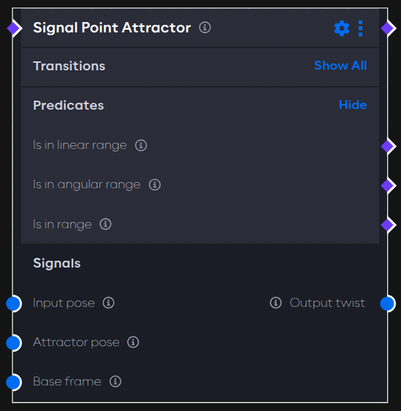
The component has three inputs and one output, all of type cartesian_state:
- Input pose: The current state of the DS, e.g. the pose used to calculate the motion towards the attractor.
- Attractor pose: The attractor of the DS, e.g. the pose towards which the motion guides the robot.
- Base frame: This input is reserved to advanced users and can be used in cases where the DS should be expressed in a moving reference frame.
- Output twist: The linear and angular velocity generated by the DS to drive the input towards the attractor.
Usually, the goal of a Point Attractor is to move a robot to a desired point in space. The predicates of the component help to detect when that is achieved such that other events can be triggered:
- Is in linear range: This predicate is true whenever the linear distance between input and attractor is below a configurable threshold (see parameters section below).
- Is in angular range: This predicate is true whenever the angular distance between input and attractor is below a configurable threshold (see parameters section below).
- Is in range: This predicate is true whenever the linear and angular range predicates are both true.
Parameters
Changing the parameters of the component will tune the response and decide at which threshold the predicates switch:
- Linear and angular gains: As shown
here, the function of the DS
contains an additional scaling constant , represented by the linear and angular gains parameters here. The higher
these values are, the higher the generated velocity. Both parameters are of type vector, so it is also possible to set
different gains per axis, or even disabling motion along some axis entirely.
warning
Setting high gains can lead to fast movements and overshoot.
- Maximal linear and angular velocity: Before publishing the output twist, the component clamps the linear and angular velocities to the values of those two parameters. This allows to increase the gains without generating an excessive response.
- Linear and angular precision threshold: The linear and angular distances from the attractor for the input to qualify as in linear and angular range (see predicates above).
Example
To set up this example, follow the steps below.
- Create a new application and record the tool frame of the robot of your choice as described here.
- In the same application, add the
Frame to Signalcomponent. Open its parameter settings, turn on auto-configure and auto-activate and set the required parameterFrameto the name of the recorded frame from step 1.tipLearn more about the
Frame to Signalcomponent here. - Add the
Signal Point Attractorto the graph and enable auto-configure and auto-activate. Then, connect thePoseoutput of the component from step 2 with theAttractor poseinput. Also connect theCartesian stateoutput of theRobot State Broadcasterin the hardware with theInput poseinput. - Add the
IK Velocity Controllerto the hardware, enable auto-load and auto-activate, and connect theOutput twistof thePoint Attractorwith theCommandinput of the controller. - Finally, make sure to load all components on start by creating the necessary event edges.
Start the application from AICA Studio, then switch to the 3D view. Drag the frame around and observe how the robot is dynamically attracted towards the frame.
Application YAML
schema: 2-0-4
dependencies:
  core: v4.4.2
frames:
  target:
    reference_frame: world
    position:
      x: 0.372464
      y: 0.048147
      z: 0.43
    orientation:
      w: -0.000563
      x: 0.707388
      y: 0.706825
      z: 0.000001
on_start:
  load:
    - component: signal_point_attractor
    - hardware: hardware
    - component: frame_to_signal
components:
  frame_to_signal:
    component: aica_core_components::ros::TfToSignal
    display_name: Frame to Signal
    events:
      transitions:
        on_load:
          lifecycle:
            component: frame_to_signal
            transition: configure
        on_configure:
          lifecycle:
            component: frame_to_signal
            transition: activate
    parameters:
      frame: target
    outputs:
      pose: /frame_to_signal/pose
  signal_point_attractor:
    component: aica_core_components::motion::SignalPointAttractor
    display_name: Signal Point Attractor
    events:
      transitions:
        on_load:
          lifecycle:
            component: signal_point_attractor
            transition: configure
        on_configure:
          lifecycle:
            component: signal_point_attractor
            transition: activate
    inputs:
      state: /hardware/robot_state_broadcaster/cartesian_state
      attractor: /frame_to_signal/pose
    outputs:
      twist: /signal_point_attractor/twist
hardware:
  hardware:
    display_name: Hardware Interface
    urdf: Generic six-axis robot arm
    rate: 100
    events:
      transitions:
        on_load:
          load:
            - controller: robot_state_broadcaster
              hardware: hardware
            - controller: ik_velocity_controller
              hardware: hardware
    controllers:
      robot_state_broadcaster:
        plugin: aica_core_controllers/RobotStateBroadcaster
        outputs:
          cartesian_state: /hardware/robot_state_broadcaster/cartesian_state
        events:
          transitions:
            on_load:
              switch_controllers:
                hardware: hardware
                activate: robot_state_broadcaster
      ik_velocity_controller:
        plugin: aica_core_controllers/velocity/IKVelocityController
        inputs:
          command: /signal_point_attractor/twist
        events:
          transitions:
            on_load:
              switch_controllers:
                hardware: hardware
                activate: ik_velocity_controller
graph:
  positions:
    components:
      frame_to_signal:
        x: 200
        y: 600
      signal_point_attractor:
        x: 660
        y: 520
    hardware:
      hardware:
        x: 1120
        y: -20
  edges:
    on_start_on_start_signal_point_attractor_signal_point_attractor:
      path:
        - x: 380
          y: 40
        - x: 380
          y: 580
    on_start_on_start_frame_to_signal_frame_to_signal:
      path:
        - x: 140
          y: 40
        - x: 140
          y: 660
    hardware_hardware_robot_state_broadcaster_cartesian_state_signal_point_attractor_state:
      path:
        - x: 620
          y: 520
        - x: 620
          y: 780