Universal Robots
Universal Robots (UR) offers a range of collaborative robotic arms in different sizes and with different payloads that are widely adopted across industries and research for their accessibility and flexibility. A graphical interface on the teach pendant allows to easily and intuitively program and integrate UR robots. At the same time, advanced users can get access to the full capabilities of the manipulators through scripting in URScript language or even by developing software add-ons, so-called URCaps.
The ecosystem around UR robots is highly developer-friendly, with open-source communication libraries, drivers, documentation, and integration support for frameworks such as ROS. Additionally, their simulation tool URSim allows developers to test and validate robot programs and interfaces without needing access to physical hardware and makes UR a popular choice building custom applications.
A guide on installing and running URSim can be found on this page.
Due to the reasons mentioned above, UR manipulators are often used for prototyping at AICA and have seen extensive internal development for robot-specific feature integration. The UR hardware collection provided by AICA comes with special tools and functionalities that are unique to UR robots. This guide intends to explain these concepts and how they can be leveraged in AICA Studio.
To use the UR collection, add the latest version of collections/ur-collection to your configuration in AICA Launcher.
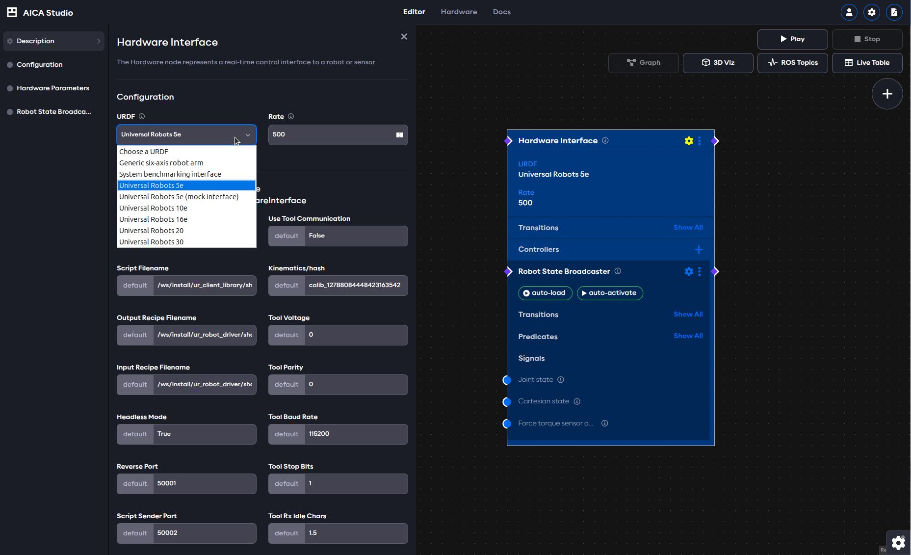
Doing this will add multiple new hardware examples as well as a few controllers to AICA Studio. All UR robots share the
same hardware interface in AICA Studio. The hardware interface has quite a large number of parameters, most of which are
not important for regular use cases.
For best results with a UR robot, always set the rate of the hardware interface to 500 Hertz, which corresponds to the control rate of the real hardware.
Local and Remote Control
The concept of Local and Remote Control on PolyScope can be easiest explained by introducing a primary and secondary device architecture. In Local Control, the controller is the primary and has full authority on loading and starting programs. In other words, the robot has to be used in person through the teach pendant and any commands sent from an external source will be rejected. On the other hand, Remote Control allows to control the robot via external sources, such as sockets, I/Os and the Dashboard Server. In this case, the controller is the secondary and external sources can load and start programs or directly send URScript commands to the controller.
Safety features remain active in Remote Control.
Choosing one of the two modes depends on the specific task at hand. During a development phase, it might be preferable to create the programs in Local Mode, whereas in a production setting, PLCs would be responsible to load and start the desired programs while the robot is in Remote Control. With the AICA System, users have the chance to get the best of both modes:
- Take full control of the robot from an AICA application (requires Remote Control)
- Run an AICA application as one node of a program (works in both Local and Remote Control)
The two examples below work out of the box with the URSim.
Full control of the robot from an AICA application
For this first case, no additional installation steps are required. The robot becomes the secondary device and all motions are coordinated through AICA Studio. Apart from setting the correct robot IP in the hardware interface, two requirements have to be met:
- On the robot, Remote Control has to be activated. For that, first activate Remote Control in the system settings as
explained here, then switch from Local to
Remote mode on the top right corner of the teach pendant. The interface automatically switches to the Run tab and
disables other tabs, indicating that control has been handed over to external sources.
- In AICA Studio, make sure that the parameter
Headless Modethat can be found under the hardware interface parameters is set toTrue. This will notify the hardware interface that it will be running headless, i.e. it is in charge of providing the full UR program to the robot controller.
Finally, implement an application of your choice in AICA Studio. An example with a joint trajectory controller is given below. Observe how the robot program status goes from Stopped to Running as soon as the hardware interface connects to the robot.
Example application, remote control
schema: 2-0-4
dependencies:
  core: v4.4.2
frames:
  wp_1:
    reference_frame: world
    position:
      x: -0.027943
      y: 0.600701
      z: 0.202217
    orientation:
      w: 0.171776
      x: 0.985056
      y: 0.002386
      z: -0.012313
  wp_2:
    reference_frame: world
    position:
      x: 0.260809
      y: 0.604927
      z: 0.194871
    orientation:
      w: 0.132343
      x: 0.95897
      y: -0.030587
      z: -0.248852
  wp_3:
    reference_frame: world
    position:
      x: 0.147083
      y: 0.552997
      z: 0.328354
    orientation:
      w: 0.012478
      x: 0.999843
      y: 0.000392
      z: -0.012536
on_start:
  load:
    hardware: hardware
sequences:
  sequence:
    display_name: Sequence
    steps:
      - delay: 2
      - call_service:
          controller: joint_trajectory_controller
          hardware: hardware
          service: set_trajectory
          payload: "{frames: [wp_1, wp_2, wp_3], durations: [1.0, 1.0, 1.0],
            blending_factors: [1.0]}"
hardware:
  hardware:
    display_name: Hardware Interface
    urdf: Universal Robots 5e
    rate: 500
    events:
      transitions:
        on_load:
          load:
            - controller: robot_state_broadcaster
              hardware: hardware
            - controller: joint_trajectory_controller
              hardware: hardware
    controllers:
      robot_state_broadcaster:
        plugin: aica_core_controllers/RobotStateBroadcaster
        events:
          transitions:
            on_load:
              switch_controllers:
                hardware: hardware
                activate: robot_state_broadcaster
      joint_trajectory_controller:
        plugin: aica_core_controllers/trajectory/JointTrajectoryController
        events:
          predicates:
            has_trajectory_succeeded:
              application: stop
          transitions:
            on_load:
              switch_controllers:
                hardware: hardware
                activate: joint_trajectory_controller
graph:
  positions:
    buttons:
      button:
        x: -460
        y: 600
    hardware:
      hardware:
        x: 620
        y: -20
    sequences:
      sequence:
        x: 40
        y: 560
  buttons:
    button:
      on_click:
        sequence:
          start: sequence
  edges:
    sequence_sequence_event_trigger_2_hardware_hardware_joint_trajectory_controller_set_trajectory:
      path:
        - x: 420
          y: 1060
        - x: 620
          y: 1060
        - x: 620
          y: 900
    sequence_sequence_event_trigger_1_hardware_hardware_joint_trajectory_controller_set_trajectory:
      path:
        - x: 240
          y: 860
    hardware_hardware_joint_trajectory_controller_has_trajectory_succeeded_on_stop_on_stop:
      path:
        - x: 540
          y: 780
        - x: 540
          y: 480
        - x: -20
          y: 480
        - x: -20
          y: 140
Run an AICA application as one node of a program
The second case requires the External Control URCap to be installed. While the robot stays the primary device, the URCap comes with a program node that allows to hand over control to secondary devices during the execution of that program node. This is especially useful for integrating smaller, single purpose AICA applications into bigger, existing cells. Once the AICA application has finished its task, it hands back control to the robot which will continue the execution of the main UR program. To set this up, follow the these steps:
- The external control URCap needs to be configured to the right remote control address. Navigate to the Installation
tab and set the address to the one of the device that will be running the AICA application.
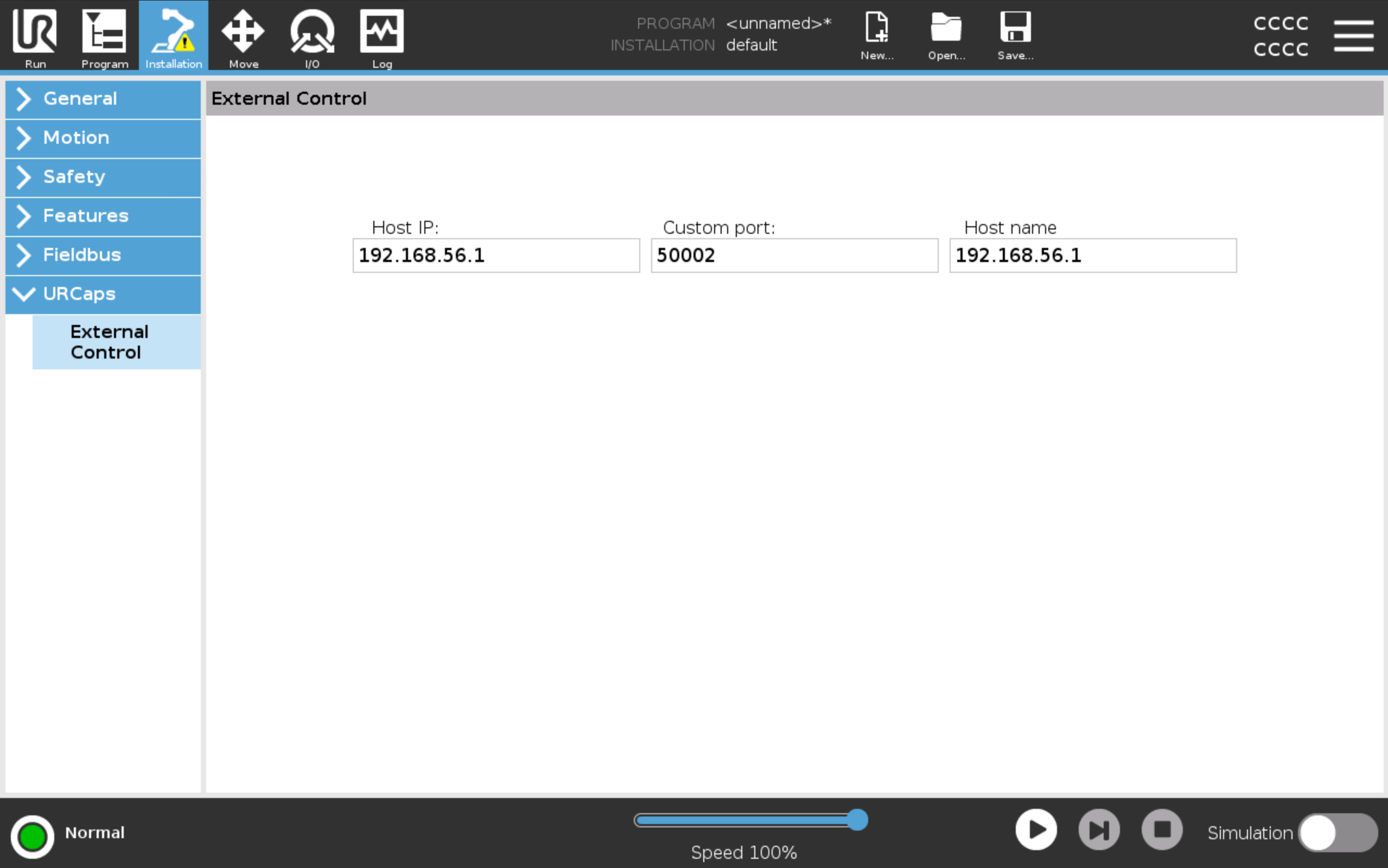
- Insert the
Control by <IP>program node from the External Control URCap at the desired location of a new or existing UR program. The robot remains in local mode.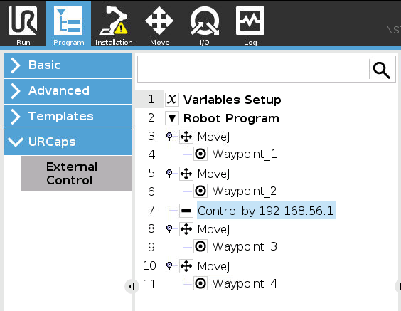
- In AICA Studio, set the
Headless Modein the hardware interfacefalse. - Still in AICA Studio, the
UR Dashboard Controllershould be added to the hardware interface. Itsprogram_runningpredicate notifies that the UR program has arrived at theControl by <IP>node and is ready to receive control commands. After completion of the task in AICA Studio, control is handed back using a service call and the UR program resumes execution. More details about this controller follow in the next section.warningSending motion commands to the robot should exclusively happen while the
program_runningpredicate is true. Activate motion controllers using this predicate and deactivate them upon handing back control.
The example with a joint trajectory controller from above is given here in its Local Control version. Be sure to start the application in AICA Studio first, and the UR program second.
Example application, local control
schema: 2-0-4
dependencies:
  core: v4.4.2
frames:
  wp_1:
    reference_frame: world
    position:
      x: -0.027943
      y: 0.600701
      z: 0.202217
    orientation:
      w: 0.171776
      x: 0.985056
      y: 0.002386
      z: -0.012313
  wp_2:
    reference_frame: world
    position:
      x: 0.260809
      y: 0.604927
      z: 0.194871
    orientation:
      w: 0.132343
      x: 0.95897
      y: -0.030587
      z: -0.248852
  wp_3:
    reference_frame: world
    position:
      x: 0.147083
      y: 0.552997
      z: 0.328354
    orientation:
      w: 0.012478
      x: 0.999843
      y: 0.000392
      z: -0.012536
on_start:
  load:
    hardware: hardware
sequences:
  sequence:
    display_name: Sequence
    steps:
      - delay: 2
      - call_service:
          controller: joint_trajectory_controller
          hardware: hardware
          service: set_trajectory
          payload: "{frames: [wp_1, wp_2, wp_3], durations: [1.0, 1.0, 1.0],
            blending_factors: [1.0]}"
hardware:
  hardware:
    display_name: Hardware Interface
    urdf: Universal Robots 5e
    rate: 500
    events:
      transitions:
        on_load:
          load:
            - controller: robot_state_broadcaster
              hardware: hardware
            - controller: joint_trajectory_controller
              hardware: hardware
            - controller: ur_dashboard_controller
              hardware: hardware
    parameters:
      headless_mode: "false"
    controllers:
      robot_state_broadcaster:
        plugin: aica_core_controllers/RobotStateBroadcaster
        events:
          transitions:
            on_load:
              switch_controllers:
                hardware: hardware
                activate: robot_state_broadcaster
      joint_trajectory_controller:
        plugin: aica_core_controllers/trajectory/JointTrajectoryController
        events:
          predicates:
            has_trajectory_succeeded:
              call_service:
                controller: ur_dashboard_controller
                hardware: hardware
                service: hand_back_control
          transitions:
            on_activate:
              sequence:
                start: sequence
      ur_dashboard_controller:
        plugin: aica_ur_controllers/URDashboardController
        events:
          predicates:
            program_running:
              switch_controllers:
                hardware: hardware
                activate: joint_trajectory_controller
            hand_back_control_success:
              application: stop
          transitions:
            on_load:
              switch_controllers:
                hardware: hardware
                activate: ur_dashboard_controller
graph:
  positions:
    hardware:
      hardware:
        x: 780
        y: 0
    sequences:
      sequence:
        x: 80
        y: 380
  edges:
    sequence_sequence_event_trigger_2_hardware_hardware_joint_trajectory_controller_set_trajectory:
      path:
        - x: 420
          y: 1060
        - x: 620
          y: 1060
        - x: 620
          y: 900
    on_start_on_start_hardware_hardware:
      path:
        - x: 440
          y: 40
        - x: 440
          y: 60
    hardware_hardware_joint_trajectory_controller_on_activate_sequence_sequence:
      path:
        - x: 20
          y: 760
        - x: 20
          y: 440
    sequence_sequence_event_trigger_1_hardware_hardware_joint_trajectory_controller_set_trajectory:
      path:
        - x: 280
          y: 920
    hardware_hardware_ur_dashboard_controller_program_running_hardware_hardware_joint_trajectory_controller:
      path:
        - x: 460
          y: 1300
        - x: 460
          y: 640
    hardware_hardware_ur_dashboard_controller_hand_back_control_success_on_stop_on_stop:
      path:
        - x: -20
          y: 1260
        - x: -20
          y: 140
    hardware_hardware_joint_trajectory_controller_has_trajectory_succeeded_hardware_hardware_ur_dashboard_controller_hand_back_control:
      path:
        - x: 680
          y: 840
        - x: 680
          y: 1380
Dashboard controller
As shown in the example above, the UR Dashboard Controller allows interaction with the UR programs to run AICA
applications as part of a bigger UR program. With the External Control program node, control can be handed over to an
AICA application. Once the AICA application has finished its tasks, control can be handed back for the UR program to
resume execution.
While this particular functionality is limited to the combination of the External Control program node in Local control
with the Headless mode set to false, other features of the UR Dashboard Controller can be used universally.
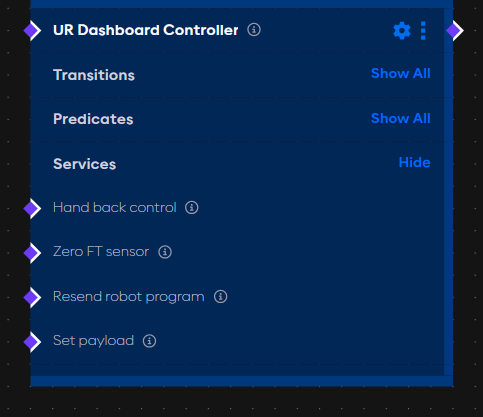
The controller provides four services:
- Hand back control: See the example above.
- Zero FT sensor: Triggering this service zeros the built-in force torque sensor.
- Set payload: If the payload of the robot changes during the application, for example by picking up an object, this
service can be used to update the payload setting on the robot. Given the mass and center of gravity, call the service
with
{mass: 1.2, cog: [0.15, 0.1, 0.05]} - Resend robot program: In case the hardware interface was launched with
Headless Modeset to true and the UR program has been stopped for some reason, this service can be triggered to restart the external control to be able to send commands to the robot again.
Apart from the services, the controller has a very long list of predicates to observe changes in (Tool) Digital Inputs
and Outputs as well as Configurable Inputs and Outputs. Additionally, it is worth mentioning the Program running
predicate, which can be used to trigger activation of motion controllers once the robot notifies that the external
control is running.
Find below another example that uses the controller to set the payload on the robot.
Example application, dashboard controller
schema: 2-0-4
dependencies:
  core: v4.0.0
on_start:
  load:
    hardware: hardware
sequences:
  sequence:
    display_name: Sequence
    steps:
      - delay: 2
      - call_service:
          controller: ur_dashboard_controller
          hardware: hardware
          service: set_payload
          payload: "{mass : 1.2, cog : [0.2, 0.2, 0.2]}"
      - delay: 2
      - call_service:
          controller: ur_dashboard_controller
          hardware: hardware
          service: hand_back_control
hardware:
  hardware:
    display_name: Hardware Interface
    urdf: Universal Robots 5e
    rate: 100
    events:
      transitions:
        on_load:
          load:
            - controller: robot_state_broadcaster
              hardware: hardware
            - controller: ur_dashboard_controller
              hardware: hardware
    parameters:
      headless_mode: "False"
    controllers:
      robot_state_broadcaster:
        plugin: aica_core_controllers/RobotStateBroadcaster
        events:
          transitions:
            on_load:
              switch_controllers:
                hardware: hardware
                activate: robot_state_broadcaster
      ur_dashboard_controller:
        plugin: aica_ur_controllers/URDashboardController
        events:
          transitions:
            on_load:
              switch_controllers:
                hardware: hardware
                activate: ur_dashboard_controller
          predicates:
            program_running:
              sequence:
                start: sequence
graph:
  positions:
    stop:
      x: 320
      y: 120
    hardware:
      hardware:
        x: 940
        y: -20
    sequences:
      sequence:
        x: 120
        y: 220
  edges:
    sequence_sequence_event_trigger_1_hardware_hardware_ur_dashboard_controller_set_payload:
      path:
        - x: 320
          y: 900
    sequence_sequence_event_trigger_3_hardware_hardware_ur_dashboard_controller_hand_back_control:
      path:
        - x: 640
          y: 860
    hardware_hardware_ur_dashboard_controller_program_running_sequence_sequence:
      path:
        - x: 100
          y: 780
        - x: 100
          y: 280
Force Mode
e-Series and UR series robots have a built-in end of arm force torque sensor that can be leveraged for force sensitive control. In UR terminology, this feature is called force mode and can be used to perform motions along a desired direction or path while being force compliant in certain axes or directions.
With the UR collection in the AICA System, we provide two controllers that very explicitly use and augment the internal force mode to behave like impedance and admittance controllers.
Impedance controller
In robotics, a true impedance controller requires direct joint torque control, a requirement not met in force mode. Yet, we can use the impedance law to translate desired displacements and velocities into a wrench command and let the robot regulate that through force mode. This enables safe interaction with the environment, making this type of control highly adapted for assembly, surface finishing and teleoperation tasks.
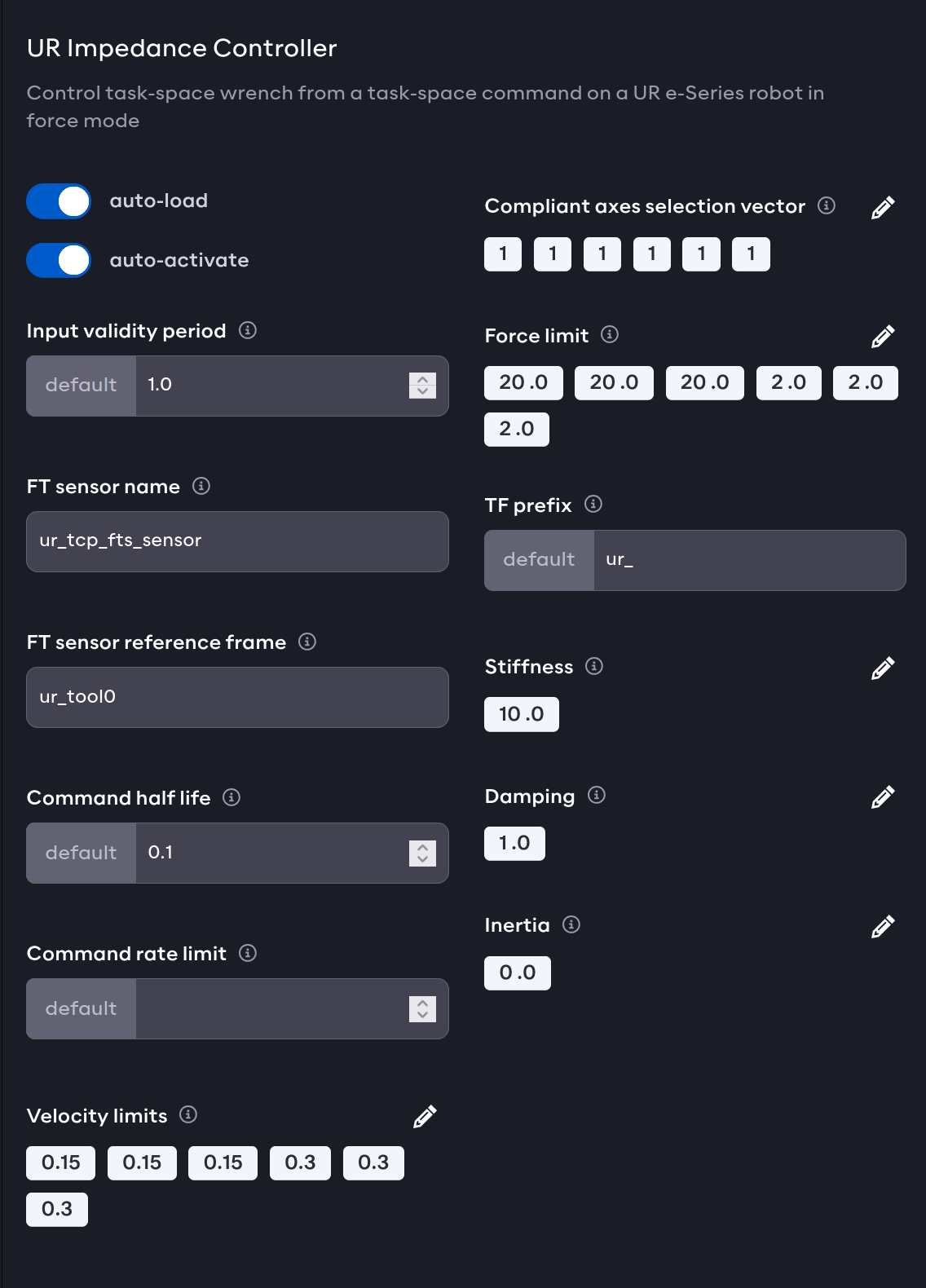
Using desired stiffness and damping parameters, the UR Impedance Controller calculates and applies a wrench in task
space from its desired and current state. By default, the controller is compliant in all directions, with the
possibility to disable certain axes individually. A valid configuration of the controller can be found in the image
below.
For the controller to operate correctly, the sensor name, sensor reference frame and force limits need to be provided.
Hand Guiding controller
Using the teach pendant with the freedrive button, operators can manually adjust the position of the robot. The
freedrive mode makes the individual actuators backdriveable but due to the different friction and stiffness, pushing and
pulling on the robot usually results in rather uncoordinated motion. To alleviate this and enable smooth trajectory
recording and kinesthetic teaching for machine learning algorithms, the UR collection comes with the
UR Hand Guiding Controller. This is a classic admittance controller that admits measured forces by transforming them
into a motion.
The controller provides additional functionality to limit and maintain the end effector pose in space. For example, this
can be used to keep the tool frame upright during teaching. As with the UR Impedance Controller the compliant axes can
by enabled and disabled individually.
For the controller to operate correctly, the sensor name, sensor reference frame and force limits need to be provided.
The controller can be further tuned and adjusted by using its parameters:
- Velocity / Force limits: The maximal desired velocities and forces that should be applied by the controller.
- Compliant axes: Selection vector for which axes should be compliant or not (1 for enabled, 0 for disabled).
- Force / Torque threshold: The thresholds above which the hand guiding is activated. Values below are considered noise.
- Hold delay: If the forces stay below the thresholds for this amount of time, hand guiding is deactivated.
- X / Y / Z limits: The spatial boundaries for the end effector motion with respect to the base frame, vectors of two values for the lower and upper limit.
- Reference orientation: A quaternion representing the desired orientation with respect to the base frame.
- Angular limit: The allowed deviation from the reference orientation.
- Linear / Angular boundary strength: If linear or angular limits are set, these values scale the response of the controller to hold the robot within the limits.
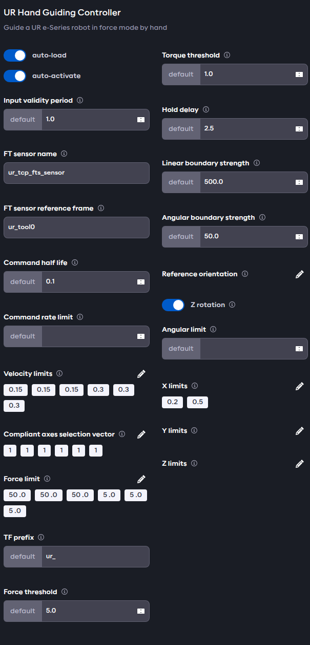
Attempts to guide the robot by pushing on individual links will fail, as the forces are measured at the sensor at the end effector.